Instructions
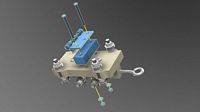
Product Demonstration and First Test: greenLean Vertical CNC Machine.
Precautions
Use a standard screw driver with a #3 tip. An automatic screwdriver or drill will cause damage to the screws or nuts that are used in the assembly. While driving the screw in with a manual screw driver, be very gentle with the process and if you feel any resistance at all, back the screw out and start again.
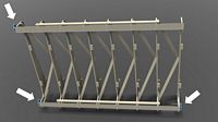
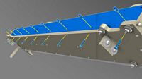
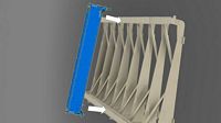
Main Rib Structure Assembly
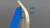
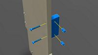
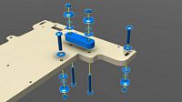
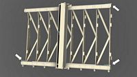
Attach rib supports to the ribs. Attach a rib support, shaped as in the illustration using two (2) 1/4 x 1.5 inch screws and two (2) cross dowels into the top of the rib at the slightly angled grooves and the side of the rib support.
The ribs and rib supports will create an eccentric bracing to eliminate any parallelogram-like flexing and keep the ribs vertical.
Using another rib support, not the same support from the previous step, attach the rib support to the lower part of the rib at the slightly angled grooves using two cross dowels and two 1/4 x 1.5 inch screws.

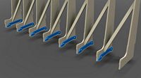
Position another rib so that the angled grooves at the mid point of the rib is against the other end of the rib supports from the previous two steps. Fasten these rib supports to this rib using four (4) 1/4 x 1-1/2 inch screws and four (4) cross dowels.

Repeat the previous three steps to attach the remaining ribs and rib supports.
Rib Feet:
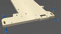
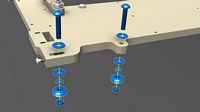
Attach a rib foot to the lower grooves on a rib using two (2) 1/4 x 2 inch screws, two (2) 1/4 inch washers and two (2) 1/4 inch nuts. Keep the screws loose so the rib feet can move up and down for adjustment later.
Repeat the previous step for each rib. The screws should remain loose until the entire rib assembly is complete (just before the gantry is installed onto the ribs assembly).
Spoilboard and wall bracket:
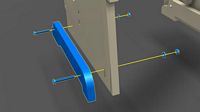
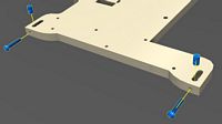
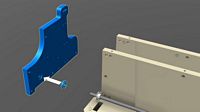
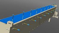
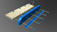
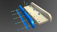
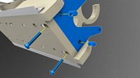
Attach one spoilboard bracket on the rib as shown using two (2) 1/4 x 1.5 inch screws and two (2) cross dowels.

Attach the remaining brackets to all of the ribs as shown. These brackets positioned at the front of the rib are intended to be used to keep the spoil board fixed to the ribs. the brackets positioned at the rear of the rib are intended to be fastened to the wall studs. Use shims behind the brackets to maintain straightness of the rib system, but attach the brackets to the wall only after the entire machine has been assembled.
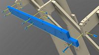
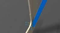
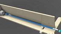
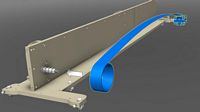
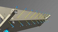
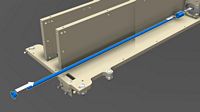
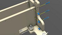
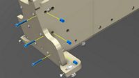
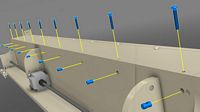
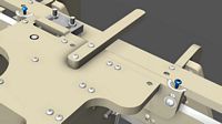
Loosely attach the X axis rail support extension using five (5) 1/4 x 1-1/2 inch screws and five (5) cross dowels.
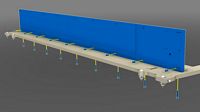
The following steps that pertain to the x-axis rail assembly are shown at the same camera angle so you can understand where each component is required.
Loosely attach the long x axis rail support using eleven (11) 1/4 x 1-1/2 inch screws and eleven (11) cross dowels.
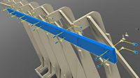
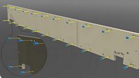
Loosely attach the long x axis rail starting from the end that contains the x axis rail support extension. This rail will span across the seam of the two rail supports. Use fourteen (28) 1/4 x 1 inch screws and fourteen (28) cross dowels.
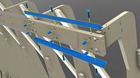
Loosely attach the shorter X axis rail extension to the long X axis rail support from the end of the long rail to the end of the rail support. Use six (6) 1/4 x 1 inch screws and six (6) cross dowels.
Repeat the X axis rail assembly steps above to complete the lower X axis rail assembly.
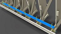
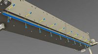
Once all of the rails and parts have been installed loosely, tighten all of the screws working from the end screws first, then at the midpoint of each screw tightening. While the tightening is in process, keep an eye on the straightness of the rail by peering down from one end of the rail to the other. the ribs may also need adjusting to keep the rails straight.

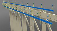
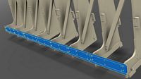
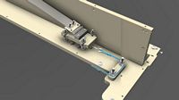
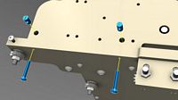
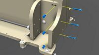
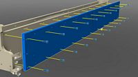
Fasten the top roller chain rest at the top of the ribs. The chain rest should be positioned so that there is equal space (ribs) on either side.. Use twelve (12) 1/4 x 1-1/2 inch screws and twelve (12) cross dowels. Make sure the orientation of the chain rest has the counter bored holes closer to the rail.
Repeat the previous step for the chain rest at the lower portion of the ribs.
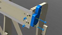
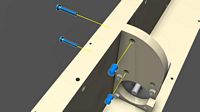
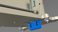
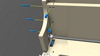
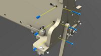
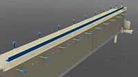
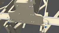
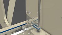
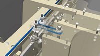
Loosely attach the chain mount to the end of the X-axis rail support using two (2) 1/4 x 1-1/2 inch screws and two (2) cross dowels.
Repeat the previous step for the remaining X axis chain mounts. When the gantry is mounted and the chain is attached to these mounts, adjust the mounts to align well with the gantry sprockets and tighten the screws holding the mounts.
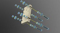
Constant Force Spring (CFS) Bearing Truck Assembly
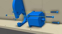
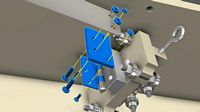
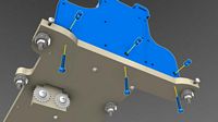
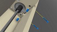
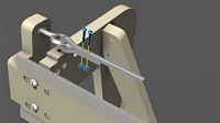
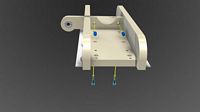
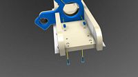
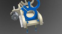
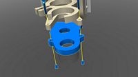
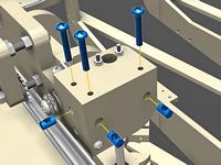
Attach the side bearings to the main bearing truck plate at each slot shown using two (2) 5/16 inch bearings (608ZZ), three (3) 5/16 inch nuts, two (2) 5/16 inch narrow washers and one (1) 5/16 x 2-1/2 inch screw. Since these are open slotted areas, tighten the two nuts at either side of the slot slightly so they will be able to move with a little bit of force and press against the sides of the gantry at a later step.
Attach the bottom bearing mount using two (2) 1/4 x 1-1/2 inch screws and two (2) cross dowels. Attach the wire rope holder eye bolt to the front of this mount using one (1) 1/4 x 2 inch eye bolt and one (1) cross dowel. Screw the eye bolt in completely.
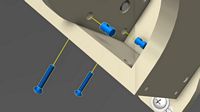
Attach the bearings at the bottom of the truck with the same configuration of hardware and bearings at the side. Tighten the nuts completely so the bearings are very secure.
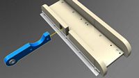
Attach the spacer and hinge to the bearing truck as shown in the illustration using two (2) #8 x 2 inch screws, two (2) #8 nuts and two (2) #8 washers. The spacer serves to rais the CFS so there is no conflict with the bearing hardware.
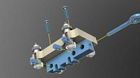
Gantry Assembly
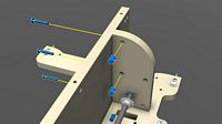
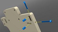
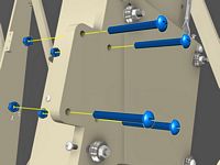
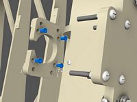
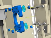
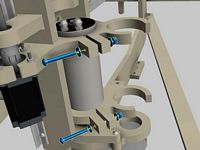
Attach the v-groove adjustment screws into the gantry bottom ends using two (2) 1/4 x 1-1/2 inch screws and two (2) cross dowels. The screw should not enter the slotted area reserved for the v-groove bearing assembly. These screws will be used for adjusting and pressing the v-groove bearing against the rail in a later step.
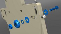
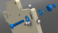
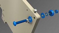
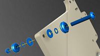
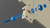
Attach the v-groove bearing assembly as shown. The bearing assembly that is installed with the wood spacer is used to guide the wire rope for the Constant Force Spring counterbalance. The other two assemblies are use for the x-axis rail. Each rail v-groove bearing assembly consists of one (1) 3/8 x 2 inch screw, two (2) standard 3/8 inch washers, one 3/8 inch narrow washer and one (1) 3/8 inch nut. The wire rope v-groove bearing assemblies do not use a washer on the screw head side as shown in the illustration and are 2" in length as the gantry bottom is counterbored. Very important: make sure the narrow washer is installed between the standard 3/8 inch washer and the v-groove bearing. The bearing will not spin if this narrow washer is not installed correctly. The narrow washer prevents the outer race of the bearing from touching the larger washer.
Install the remaining v-groove bearing assemblies for this side of the gantry bottom.
Repeat the previous steps for installing the adjustment screws and v-groove bearing assemblies.
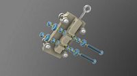
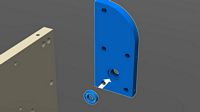
Fasten the gantry back to the gantry bottom using nine (9) 1/4 x 1-1/2 inch screws and nine (9) cross dowels. Pay close attention to the orientation of this gantry back using the large hole on the gantry back and the square hole on the gantry bottom as a reference.
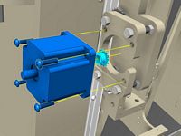
Using three (3) 1/4 x 1-1/2 inch screws and three (3) nuts, fasten the NEMA 34 (Large) stepper motor to the x-axis motor mount as shown in the illustration. The motor mount does not need to be placed in this location for this step. Make sure the wire outlet on the motor is facing up.
Attach the x-axis motor mount to the gantry back using two (2) 1/4 x 1-1/2 inch screws and two (2) cross dowels.
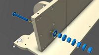
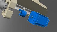
Insert a 1/2 inch to 1/2" rigid coupling to the NEMA 34 motor rear shaft. Don't tighten the coupling until a after the roller chain is installed on the gantry at a much later step. Insert one of the two 1/2 inch rods into the other side of the coupling. Slide the drive pulley onto the rod in the orientation shown in the illustration.
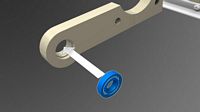
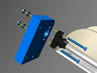
Insert one (1) 1/2 inch ID (inside diameter) bearing into the bearing seat on the x-axis bearing support. the bearing may need persuasion to be inserted into the seat. You can use a vice or clamp, or use a mallet, or a hammer to bring the bearing into the seat. If a hammer or clamp/vice is used, use a piece of wood to protect the bearing in this process.
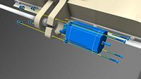
Attach the bearing support to the gantry back using two (2) 1/4 x 1-1/2 inch screw and two (2) cross dowels. To place the bearing support into the proper location, the rod will need to be inserted into the bearing first and then moved axially into place.
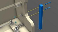
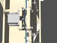
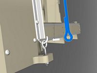
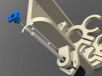
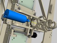
Install the constant force spring axle assembly to the gantry back using the 1/2 x 5 inch screw, one (1) 1/2 inch washer, four (4) 1/2 inch nuts and three (3) 1/2 inch ID bearings. the nuts will need to be tightened around the bearings in the most appropriate way to bring as much surface area as possible to the constant force spring.
CORRECTION The 1/2 x 5 inch screw is different than pictured. The actual screw will be threaded and does not have a head.
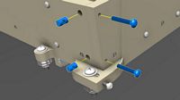
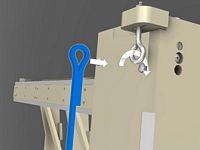
Attach the constant force spring to the hinge of the bearing truck using a plexiglas adapter, two (2) 1/4 x 1 inch screws, two (2) 1/4 inch nuts, two (2) #8 x 1/2 inch screws and two (2) #8 nuts. The plexiglas part is sandwiched by the hinge and the constant force spring end that exhibits two mounting holes.
Instructional Video: Coiling the Constant Force Spring
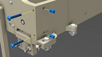
Position the constant force spring and bearing truck. The loop of the constant force spring should be wrapped around the constant force spring axle. The bearing truck and constant force spring will be tightly bound at this point. Both springs will be used in the same location.
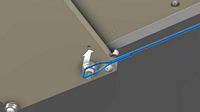
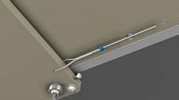
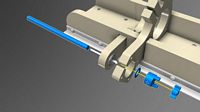
Attach one end of the wire rope to the eye bolt with a ferrule. Thread the end of the wire rope through the eye of the eye bolt and curl it around. Use a ferrule to hold this loop of wire rope together. Crimp the ferrule tightly to provide a very secure hold on this loop with a crimper, wrench, clamp or vice grips. Make sure the crimp is very tight. You can optionally use an extra ferrule (not included) to wrap the tail of the end of the wire rope back on itself for a more secure hold if desired; however, this will need to be planned and done prior to the crimping.
To keep best management of the wire rope during the next many steps, route the wire rope around the v-groove bearings as shown and tape the remaining wire rope to the body of the gantry and also on the v-groove bearings so the wore rope does not become removed from the groove.
Fasten twenty two (22) 1/4 inch nut inserts with an allen wrench into the gantry front. The holes reserved for these insert nuts are slightly smaller than the holes reserved for cross dowels. Also, all of the cross dowel holes will exhibit an intersecting hole and the insert nut holes will have no intersecting holes.
Attach the gantry front to the gantry bottom using nine (9) 1/4 x 1-1/2 inch screws and nine (9) cross dowels. Make sure to orient the side wit the nut inserts toward the inside of the gantry. The 3 inch square opening is at the bottom and closest to the constant force spring axle.
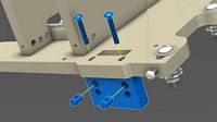
Attach an idler sprocket mount to the gantry bottom using two (2) 1/4 x 1-1/2 inch screws and two (2) cross dowels.

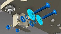
Fasten the idler sprocket assembly to the idler sprocket mount using two (2) 3/8 x 2 inch screws, two (2) idler sprockets, two (2) 3/8 inch narrow washers, two (2) 3/8 inch standard washers and two (2) 3/8 inch nuts. Make sure to attach the idler sprockets on the side facing the end of the gantry. Additionally, the narrow washers much be positioned between the standard washers and the idler sprockets; otherwise, the idler sprocket will not spin.
Repeat the previous two steps to attach the idler sprockets and mount to the other side of the gantry.
Make sure these idler sprockets are attached to the side shown and not the side facing the end of the gantry.
Couple the other 1/2 inch rod to the face of the motor using one (1) 1/2 inch to 1/2 inch rigid coupling and one (2) 1/2 inch rod. Slide one (1) drive sprocket onto the 1/2 inch rod in the orientation shown.
Insert one (1) 1/2 inch ID bearing into the gantry side that exhibits a bearing seat. Use the same method of bearing insertion as previously stated for the other bearing mount.
Attach the gantry side used in the previous step to the gantry bottom using two (2) 1/4 x 1-1/2 inch screws and two (2) cross dowels.
Attach the same gantry side to the gantry back using three (3) 1/4 x 1-1/2 inch screws and three (3) cross dowels.
Attach the same gantry side to the gantry front using three (3) 1/4 x 1-1/2 inch screws and three (3) cross dowels.
Attach the other gantry side to the gantry bottom using three (3) 1/4 x 1-1/2 inch screws and three (3) cross dowels.
As with the previous gantry side, fasten this gantry side to the gantry back and front using the same hardware.
This part serves as a mount for the cable carrier at the top of the gantry and top of the ribs structure. Attach this part to the top gantry side (the gantry side closest to the wire rope bearings). Use two (2) 1/4 x 2 inch screws and two (2) 1/4 inch nuts. The gantry front is shown transparent for a better view to the nuts.
Attach the Y axis rail support to the gantry front using twenty two (22) 1/4 x 1 inch screws. These screws will be threaded into the nut inserts that were previously fastened to the gantry front. be very careful screwing these screws into the nut inserts. If there is any slight misalignment with the nut, the screw and nut will be damaged and will not be effective. Follow the precaution stated at the beginning of these instructions.
Attach the Y axis rail support to the gantry side using three (3) 1/4 x 1-1/2 inch screws and three (3) cross dowels.
Attach the Y axis rail support to the other (lower) gantry side using the same hardware from the previous step.
Attach the gantry top to the gantry front using ten (10) 1/4 x 1-1/2 inch screws and ten (10) cross dowels. The cross dowel holes are accessed through slightly larger holes on the Y axis rail support. Be very careful not to push the cross dowel too far as to lose the cross dowel in the inaccessible cavity of the gantry. If cross dowels do get pushed in, just raise the lower end of the gantry and allow the cross dowel to roll to the top end and out of the openings around the wire rope v-groove bearings.
Attach the gantry top to the gantry back using nine (9) 1/4 x 1-1/2 inch screws and nine (9) cross dowels.
Fasten the bottom Y axis rail to the bottom of the Y axis rail support using ten (10) 1/4 x 1 inch screws and ten (10) cross dowels. Keep an eye on the alignment of the rail by peering down the rail from one end as you tighten the screws.
Fasten the top Y axis rail to the top of the Y axis rail support using ten (10) 1/4 x 1 inch screws and ten (10) cross dowels. For alignment, refer to the previous step.
Attach the gantry rear support to the gantry bottom using nine (9) 1/4 x 1-1/2 inch screws and nine (9) cross dowels.
Attach the X axis motor mount to the gantry rear support using two (2) 1/4 x 1-1/2 inch screws and two (2) cross dowels.
Fasten the X axis bearing support to the gantry rear support using two (2) 1/4 x 1-1/2 inch screws and two (2) cross dowels.
Fasten the lower gantry side to the gantry rear support using two (2) 1/4 x 1-1/2 inch screws and two (2) cross dowels.
Fasten the top gantry side to the gantry rear support using two (2) 1/4 x 1-1/2 inch screws and two (2) cross dowels.
This step may require a couple people to complete. Rest the top bearings of the gantry onto the top X axis rail. Make sure the top bearings are loose enough to move within its slot. Also, make sure the X axis rail supports are loosely fastened to the ribs so the X axis rail support have some play up and down.
Once the upper bearings are resting on the top rail, align the top of the bottom set of bearings onto the top of the bottom X axis rails. Move the bottom X axis rails up against the bearing so that the bottom bearings are in-line with the bottom rail.
Gently tighten the v-groove adjustment screw at the top of the gantry. Only use slight tightening. Over tightening will damage the rail. A good rule of thumb is to spin the v-groove bearings while tightening. When the v-groove bearings stop spinning and the gantry moves when you try to turn the bearing, the screw will be tight enough.
Repeat the process from the previous step to tighten the lower bearings.
Errata: Use two (2) of the thumb screw provided since there will be very little space for a screwdriver to fit between the floor and the gantry side.
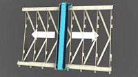
Move the gantry to the far left of the ribs structure and tighten only the leftmost screws on the top and bottom rail supports. Move the gantry to the far right and tighten the rightmost screws of the top and bottom rail supports. As you complete this process, keep an eye on the alignment and straightness of the rails by peering down the rail from one end.
Repeat this process by tightening the rail supports at the mid point of each tightening. For instance, the next tightening will by at the midpoint of the X axis rail, so the gantry is moved to the midpoint and the screws at the midpoint (next to the gantry) are tightened.
Ss you secure the X axis rail supports and you notice an issue with straightness, loosen the X axis rail support and repeat the above process.
Route the lower X axis roller chain over the drive sprocket and under the idler sprockets using the longer roller chain in the kit. Make sure the drive sprocket is loose during this installation. The drive sprocket will not be tightened until the roller chain is fixed at both ends and the gantry is moved to make sure the drive sprocket is well aligned with the sprockets.
Repeat the previous step for the roller chain at the top of the gantry.
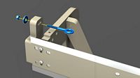
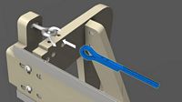
The eye bolt will serve as the tie to fix the end of the roller chain. Install the eye bolt assembly using one (1) 1/4 x 2 inch eye bolt, one (1) 1/4 inch washer and one (1) 1/4 inch nut.
Affix the roller chain to the eye bolt using two (2) # 4 x 3/4 inch screws and two (2) #4 nuts. Thread the end of the roller chain through the eye of the eye bolt and curl the roller chain around to itself and fasten the chain within the links using the #4 hardware.
Fasten the end of the roller chain using the #4 hardware as shown.
Repeat the previous steps to complete the remaining eye bolts and roller chain ends. During this process, make sure that the drive sprockets and the couplings around the X axis are loose so when the roller chain is tensioned, those mechanical parts can move freely and not cause the gantry to rack.
Tension the roller chain so there is little deflection on the chain, but don't tension the chain too much.
ZY Plate Assembly
Attach the v-groove adjustment screws to the ZY plate using one (1) 1/4 x 1-1/2 inch screw and one (1) cross dowel for the top and one (1) 1/4 x 2 inch screw and one (1) cross dowel for the right side.
Attach a v-groove assembly on the ZY plate using one (1) 3/8 x 2 inch screw, one (1) v-groove bearing, one (1) 3/8 inch nut, one (1) 3/8 inch narrow washer and two (2) 3/8 inch standard washers.
Repeat for this and the next steps pertaining to installing the adjustment screws and single v-groove bearing assemblies. Use two 3/8" standard washers on the bearing side instead of one.
Use two 3/8" standard washers on the bearing side instead of one.
Since this assembly uses two v-groove bearings, the 3/8 screw will need to be 2-1/2 inches rather than 2 inches as in the previous steps. Make sure to place the washers in the order shown so the bearing will spin correctly. Use two 3/8" standard washers on the back bearing side (left side on the illustration) instead of one.
After this bearing is attached to the ZY plate as shown in the illustration, attach the entire ZY plate to the gantry rails and gently tighten the v-groove bearings against the top rail with the adjustment screws as was done for the gantry. Remember not to over tighten as the rail can be damaged as a result. Use two 3/8" standard washers on the back bearing side (the bearing on the left on the illustration) instead of one.
Affix the other end of the wire rope to the hole provided on the ZY plate. Thread the wire rope through the hole and curl the wire rope though to meet itself.
Slide the ferrule over the rope end and crimp the ferrule. Refer to the previous wire rope connection onto the constant force spring bearing truck to determine how to crimp the ferrule.

Attach the anti-backlash nut mount support to the ZY plate using one (1) 1/4 x 1-1/2 screw and one (1) cross dowel.
Add four (4) 3/8 x 3 inch screws and four (4) 3/8 inch nuts to the ZY plate as shown. These screws will serve as the main screws to hold the Y axis stepping motor mount and idler sprockets.
Using four (4) 1/4 inch nut inserts, fasten these nuts into the Y axis stepping motor mount as shown.
Fasten the Y axis stepping motor mount and idler sprockets to the four screws using six (6) nuts and two (2) idler sprockets.
Errata: Include two 3/8" nuts on the 3/8" screws that will receive the idler sprockets. These nuts will hold the idler sprockets in place. Between the idler sprockets and the Y-Axis motor mount, add a 3/8" standard washer against the mount and a 3/8" narrow washer between this washer and the idler sprocket. This will enable the idler sprocket to spin freely and the not washer combination will hold the idler sprocket securely in place.
Attach the drive sprocket to the shaft of the Y axis stepping motor and mount the stepping motor to the stepping motor mount using four (4) 1/4 x 1 inch screws.
Attach the eyebolt to the Y axis top chain mount in the same configuration as the X axis chain mount eye bolt. Loop one end of the Y axis roller chain through the eye bolt.

Attach the roller chain to the eye bolt using two (2) #4 x 3/4 inch screws and two (2) #4 nuts.
Route the Y axis roller chain below the idler sprockets and above the drive sprocket.
Repeat the previous steps to attach the lower roller chain end for the Y axis. Tension the roller chain snugly and run the ZY plate up and down to auto adjust the drive sprocket on the stepper motor shaft and then tighten the drive sprocket very tightly.
Attach Z axis rail to the z-axis side and rail support using five (5) 1/4 x 1-1/2 inch screws and five (5) cross dowels. Pay close attention to the orientation of the z-axis rail support.
Repeat the process for this side of the z-axis. Again, pay close attention to the orientation of the rail support and the side piece exhibiting the special cutouts for the motor and bearing mounts.
Insert the bearing into the Z axis bearing mount using the same technique used in the X axis bearing mount/
Insert the bearing mount through the hole of the Z axis side as shown and line up the holes for the next step.
Attach the Z axis bearing mount to the Z axis rail support using two (2) 1/4 x 1-1/2 inch screws and two (2) cross dowels.
Attach the stepping motor and top spindle mount to the Z axis rail support using two (2) 1/4 x 1-1/2 inch screws and two (2) cross dowels.
Assemble the drive mechanics to the Z axis assembly using one (1) 1/2 inch lead screw, one (2) 1/2 inch narrow washer, one (1) 1/2 inch flexible coupling hub and one (1) flexible coupling spider. Insert the lead screw through the 1/2 inch ID bearing. slide the washer over the lead screw and fasten the coupling hub so that the end of the lead screw is flush with the other side of the hub.
Errata: Add a 1/2" bearing, 1/2" narrow washer and a 1/2" collar to the other side of the bearing mount on the lead screw. This will stabilize the lead screw axially. Make sure the bearing is against the bearing mount and the washer is between the bearing and the collar so the outer race does not rub against the collar.
Insert the Z axis stepper motor into the 1/4 hub where the shaft is flush with the other side of the hub and tighten the set screw.
Fasten the Z axis stepper motor to the Z axis motor mount using four (4) #8 x 1-1/2 inch screws, four (4) #8 nuts and four (4) #8 washers.
Attach the lower spindle mount to the Z axis rail support using two (2) 1/4 x 1-1/2 inch screws and two (2) cross dowels.
Attach the dust shoe holder to the Z axis rail support using two (2) 1/4 x 1-1/2 inch screws and two (2) cross dowels.
Secure the dust shoe to the dust shoe holder using two (2) 1/4 inch nut inserts and two (2) thumb screws.
Thread the anti-backlash nut onto the lead screw. When applying the nut to the screw, hold the bushing back allowing the nut to spread and be threaded onto the lead screw. The nut will hold to the lead screw very firmly and will require a few runs up and down the entire lead screw to break it in. Make sure to align the nut properly so that there is no cross-threading.
Loosely fasten the anti-backlash nut to the anti-backlash nut support with two (2) #8 x 1-1/2 inch screws, two (2) #8 nuts and two (2) #8 washers.
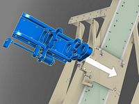
Slide the entire Z axis assembly between the bearings of the ZY plate. Allow the anti-backlash nut mount to rest on the anti-backlash nut mount support that is attached to the ZY plate. At this point, the bearings can be gently tightened against the Z axis rail using the adjustment screws for the v-groove bearings.
Secure the anti-backlash nut mount to the anti-backlash nut mount support using three (3) 1/4 x 1-1/2 inch screws and three (3) cross dowels.
Insert the spindle into the spindle mounts as shown. Adjust the depth of the spindle so that the top of the spindle is very close to the top spindle mount, but the collet is flush or below the bottom surface of the dust shoe.
Secure the spindle with two (2) 1/4 x 2 inch screws, two (2) 1/4 inch nuts and four (4) 1/4 inch washers.
Tutorial: How to install the spoilboard to the greenLean ribs.