Price Options Your Cart
Vacuum Pressure Controller
Price Options Your Cart
Vacuum Nozzle and Vacuum Cups
Vacuum Nozzle and Cups for SMD Pick and PlaceThis is a tool to serve as a pick up for SMD parts and placing them on a PCB board. This part accepts a tube to connect to a vacuum source and a tip to pick up small parts. If larger SMD parts are needed to be moved, vacuum cups are included for this purpose.
Price Options Your Cart
redFrog Pick and Place Machine Kit
--
The following information is kept on this page for historical reasons)
A few points of update: the software used for all ofthge pick and place is EMC2
running under Ubuntu Linux. The control language is g-code and almost every feature
of this language was used to make the final control easy to use. Three main sub
g-code programs have ben created. The main g-code subroutine contains all of the
camera offset, feed specifications, rotation compensation and the levels of various
places on the machine. The tape and banks are held in another file that defines
their x and y part locations for picking. The final subroutine takes care of tool
changes (vacuum cup changes). The main file that users will have the most interaction
with is a file that contains all of the place locations, orientaion specs and choice
of tape from which to pick that part. There were many days of exhaustive programming
(many frustrating moments) in g-code to make sure the end user would have as little
to enter as possible. I took advantage of using variables with meaningful names,
global variables, subs and calls, and conditional statements in g-code. All of this
functionality can be used with mach3; however, I have not found a good webcam program
that includes crosshairs. Camview in Ubuntu works well in this case.
An example line looks like this:
o<PickPlaceV2> call [.062] [1] [#<_X-B1-R1-8>] [#<_Y-B1-R1-8>]
[0] [90] [1.5432] [2.5234] [135] [.02]
Specifically, this is:
- [.062] Tape cavity length
- [1] How many positions to feed (sprocket holes... 1, 2, 3 etc..)
- [#<_x-b1-r1-8>] X-bank and reel to get the part and the mm tape width
- [#<_y-b1-r1-8>] Y-bank and reel
- [0] A y-offset if needed to be able to get a perfect pick on the part
- [90] Orientation of the pick
- [1.5432] X place location
- [2.5234] Y place location
- [135] Place orientation
- [.02] Part thickness
The processes to fill add lines:
- Making sure the machine is homed at the correct location, move the machine to the
correct place location (crosshairs centered at the component location).
- Add a new line with place location, bank and reel, part thickness, part cavity length
and orientations (example above).
- Do a dry run to determine if the correct placement and pick was done. If the place
is off, then the place x and y would be nudged. I generally nudge it .01" in either
direction to get it perfect.
The initial configuration, camera offsets and bank and reel definitions are that
most difficult part of the process, but it is a one time activity. Thereafter, the
definitions file, offsets and compensations can be tweaked from time to time to
make the picking and placing more accurate over an initial "getting to know" period.
Main Information:
Here is a pick and place machine for moving SMD (Surface Mount Device) components
from reels or waffles to PCB (Printed Circuit Board). The machine is relatively
small in size with rapid movement. This pick and place machine is aimed at the cottage
industry and garage DIYers and will carry a very low price.
Stages complete:
- Overall 3 axes movement, structure and mechanics
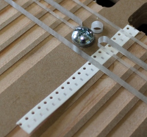
- Method for reel tape alignment and positioning (scrapped first method, see video).
- Clamping and positioning of PCBs
- Software (EMC2 with hand written g-code). I will provide a tutorial on this. It's
really easy... I promise.
- Vacuum
selection (inexpensive and quiet).
- Procurement of tube fittings and silicone tubing.
- Pneumatics (not for movement, but for suction) and installation.
- Testing
Stages to complete:
- Assembly videos footage edited and posted
- Offer various options on the website
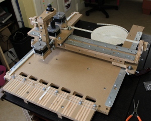
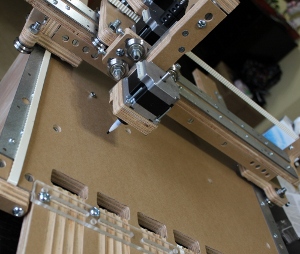
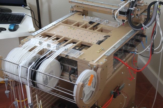
Old prototype photos:
Here are some sneak peek photos of the upcoming pick and place machine called the
redFrog.