We have a new look.
Let us know what you think.
CNC Router Kit Version 4.0:blackToe 2'x4'
blackToe 2'x4' routing area Version 4.0 CNC Machine Kit
This selection does not include the optional table listed below.
blackToe 2'x4' routing area Version 4.0 CNC Machine Kit without electronics
See the section below for an itemized part list with prices.
Optional Table
See the section below for a short video on the parts configuration.
About the blackToe 2x4 Version 4.0:
A new toy for The
Next Industrial Revolution!. Everyone with a garage (or a spare bedroom)
can get serious with their creations on the cheap. Version 4.0, a solid, fast, attractive
chain driven CNC machine. This CNC machine offers 3 axis functionality driven by
roller chain and sprocket for the x and y axes and lead screw for the z-axis. The
overall structure is solid with respect to stresses in all directions. Chain drive
for this CNC machine will allow velocities into the 800 to 1000 ipm (inches per
minute) range. Unlike the previous version, a table is offered as an optional add-on.
The first difference you will notice from the previous version (2.2) is the structure.
Structure for rigidity is one of the most important factors in the design of these
machines. Notice how the main y horizontal spans also serve to add rigidity for
y axial stresses (lateral forces) by wrapping around the gantry side. This condition
of adding structure to the gantry sides exists on both sides and are fastened into
the gantry side in two directions for added stability.
As a trained designer, aesthetics was hugely important in the development of these
CNC Machines. The version 4.0 in my opinion has some nice industrial design features.
All of these design implementations were added keeping the function and structure
in mind. The placement of the idler sprockets in line with the drive sprocket is
one such aesthetic design approach. The x-axis motor (as in the blueChick) is hidden
from view by the back structural support. All of the parts that make up this CNC
machine design was formed with a keen eye on aesthetics.
The x-axis stepping motor is located within the mid point of the gantry as opposed
to the lower portion of the gantry sides. Also markedly different with the previous
blackToe CNC machines, there is only one x-axis motor. The mount for the x-axis
motor can accept either a NEMA 23 frame or a NEMA 34 frame if more power is desired.
The location of the x-axis motor allows the machine to extend shafts to both sides
of the gantry to drive two roller chain systems (keep the gantry square and eliminate
any racking). This has a couple of advantages: the gantry is squared only one time.
Previous versions required a squaring at machine startup. Second, by having the
x-axis motor above the machining and not below the table, cabinets, or other types
of structure can reside under the table.
The z-axis can reach 5-7/8 inches (149.225 mm) of travel. The entire z-axis mechanism
has bee revamped in line with the blueChick CNC Machine. Unnecessary leadscrew length
has been removed by locating all bearings and at the top of the axis. At the full
down position, the top collar is touching the lead nut and at the full up position
(where the end of the rails meet the lower bearing) the end of the lead screw meets
the lead nut.
As with the previous versions, the z-axis uses an anti-backlash nut mated with a
1/2 inch lead screw. the lead screw specifications: 1/2 inch diameter, ACME precision
thread, 10 threads per inch at 5 starts which translates to two (2) turns per inch.
With very complex carving, the z-axis can handle fast up and down movements and
remain at a relatively low motor rpm to increase torque at these speeds.
One of the more interesting enhancements in the version 4.0 is the vacuum attachment.
The same upper holder remains in this version, but the lower vacuum mount is completely
re-designed. The vacuum mount now re-directs the air flow from the center point
of the router (where the end mill or router bit is located) to the vacuum hose.
Now, a brush, or plastic shield can be installed right around where the cutting
happens.
By re-directing the air in this way, there is the added benefit to helping cool
the router motor. Router motors have a fan attached to the lower part of the housing
that spins using the router motor. This acts as a cooling element and a method of
blowing chips out of the way so there is visual clearance while hand routing. Since
there is no hand routing here, blowing the chips everywhere is not the best thing.
Instead, the blowing is blocked by the bottom of the vacuum mount and is re-directed
into the vacuum along with the chips. The vacuum may also remove any debris that
may enter the router motor.
All of the stepping motors are in close proximity to each other. Wiring is much
simpler with this CNC machine. The z-axis stepping motor wires can be routed towards
the y-axis stepping motor. At the y-axis stepping motor, both the y-axis stepping
motor wires and z-axis stepping motor wires can be routed towards the point where
the x-axis stepping motor wires exit the gantry box. From that point, all of the
wires can be routed to the stepping motor drivers.
Roller chain is kept as the main drive mechanism and transmission of linear motion
due to its great characteristic of low maintenance and low to no backlash. The roller
chain drive system has decreased in size for this version. Instead of using #40
chain as in the previous version, this machine is using #25 chain. The difference
between these two sizes is mainly the pitch. The pitch is the distance from one
link to the other, or from the crest of a sprocket to the next crest (a crest is
the high point of a tooth of a sprocket). The pitch for the #40 chain is 1/2 inch
(12.7 mm) and the pitch for the #25 roller chain is 1/4 inch (6.35 mm). There are
two main reasons for changing the roller chain size. First, the #40 chain is heavy.
In reality, the #40 chain is perfectly fine for these machines, but the weight requires
high tension to be applied to the chain, which requires more structure to keep the
chain in tension. The #25 roller chain is relatively light and can tension very
easily. The second reason is the effective increase in resolution. The resolution
for the #25 chain in relation to the #40 chain is doubled. Resolution is very important
with CNC machines when PCB fabrication or intricate carving is required. Even though
the #40 chain can be microstepped using the drivers to increase the resolution,
the torque is reduced at higher microsteps. The #25 chain is a great balance with
keeping torque high and maintaining a very high resolution.
Let's go ahead and do the math to determine the resolution (steps per inch). A standard
stepping motor provides 200 steps per revolution (1.8 degrees per step). It's never
recommended to set a driver for full step, so let's assume that the drivers are
set to 1/16 microstepping for the stepping motors that are to drive the chain (not
the lead screw). I generally recommend 1/16 for microstepping roller chain drives.
There will be 16 steps for each full step. Simply multiply 200 steps per revolution
by 16 and you get 3200 total steps per revolution. The sprockets that I use on this
machine has 9 teeth. At the pitch of 1/4 inch, one entire revolution will yield
2.25 inches. Since we are looking for step per inch, we already know how many steps
there are in one revolution, so all we need to do is divide the 3200 steps with
the number of inches in one revolution (2.25 inches). So, 3200 steps per revolution
divided by 2.25 inches is 1,422.2222 steps per inch.
For the lead screw, I recommend 1/4 microstepping. So, 200 steps per inch multiplied
by 4 steps (per full step) is 800 steps per revolution. With lead screws, the math
is a bit reversed since the mechanism is actually increasing the resolution. The
lead screw, as mentioned above, yields 2 turns per inch. Since we are going the
other way and the mechanism is multiplying the resolution, we need to multiply the
steps per revolution by the number of turns per inch (2). So, the product of 800
and 2 is 1600. Another way to think about this (similar to the roller chain math)
is to divide 800 by the number of inches in one turn, which is 1/2 inch. so, 800
divide by .5 gives us the same answer, 1600 steps per inch. you can increase both
the roller chain and lead screw numbers by increasing the microstepping. Make sure
to understand the torque at higher settings.
For the first time, the table is an option that can be included as an option. The
table has four main parts that is assembled with ribs below similar to a torsion
box, but will still need to be placed on a flat surface. For best results, the table
assembly should be glued together and another full piece be glued to the bottom
to create a full torsion box. To really take advantage of space, cabinets and/or
drawers can be placed under the machine. Casters below that would allow for the
machine to be somewhat mobile.
MDF has been replaced with birch plywood. This plywood has little to no voids and
is stronger than MDF. The birch is also lighter than the MDF which could be less
expensive for international shipments.
Parts not included:
- Computer (Personal Preference)
- Software (Personal Preference)
- Router (Personal Preference although I recommend Porter Cable 2.25 HP 800 series)
Shipping:
- International shipments require a $600 deposit. This amount is subtracted with the
actual shipping charges and the difference is refunded. Charges do not include duty,
customs, tarriffs, or any of the other surprises that are associated with international
shipments.
- If paypal does not ask for your shipping address, please email me your address using
this form (the Contact Us page).
blackToe Assembly Instruction Videos:
With these videos, we made a great effort to reduce the amount of assembly per video.
This means there will be more videos, but less information per video. This will
allow a more efficient process of assembly. If there was a particular part of an
assembly that was missed, or need to return to at a later date, it will be much
easier to find the steps to accomplish the desired task.
To see the wiring videos for the electronics, go here.
Table construction:
The following information is provided to help in a custom table build. These images
demonstrate the recommended method for the table construction. The overall table
is a simple structure as the base with a shelf and the main table and surface is
is a torsion box table. The name torsion box describes the internal ribbing sandwiched
by two layers of boards. This technique of ribbing resists torsion (twisting) of
the table so that the entire table will be level in any direction.
To insure this the table will need a surface that is dead level. The best way to
do this is to use winding sticks and a level on a surface that can be leveled with
shims. Winding sticks are used to make sure there is no torsion existing in the
base when starting the construction. these winding sticks are placed at each end
of the board and just be looking at the two winding sticks from one end, the torsion
can be identified and corrected. This is best see in the videos from the
Wood Whisperer or David Marks.
Torsion Box - as designed and built by David J. Marks
from Golem Online on
Vimeo.
There are a couple of aspects that must be followed: The table must have a width
between 26-3/4" and 27", there must be an overhang of at least 1" (I recommend 1-1/2")
along the sides and there must be a clearance of 1-3/4" from the edge of the table
to the start of the rail.
In the image to the left, the table has a dimension of 6 feet by 2 feet and 2-3/4".
the 2' 2-3/4" is 26-3/4". This is a minimum dimension for the width so the gantry
will fit correctly.
The 6 feet can be longer or shorter; however, since the gantry side is about 17
inches in length, this takes away from the x-axis travel, so the table should be
at-least 18 inches longer in the x-axis direction. I recommend that 2 feet be added
to the x-axis length so there is some wiggle room at both ends.
The table length can be increase according to the desired x-axis travel length.
For example, if the desired x-axis travel is 8 feet, the table length should be
10 feet to compensate for the gantry structure.
Since the x-axis rails need to be fastened to bot the top and bottom sides of the
table, the top surface should overhang 1-1/2" on both sides. This means that the
torsion box, or the structure just below the table surface should be a maximum of
23-3/4" so that this clearance can be established. The table top should be 3/4"
in thickness.
To make room for the parts that hold the x-axis chain, the rails should start 1-3/4"
from the edge of the table and provide the same clearance at the other end.
The following set of inages show one example of a table that would work as a base
for the 2x4 blackToe CNC Machine. There are many possible variations (table without
torsion box, cabinetry under table, etc.). This deminstrates an example for use
as a possible method, but I would encourage differernt table structures and features.
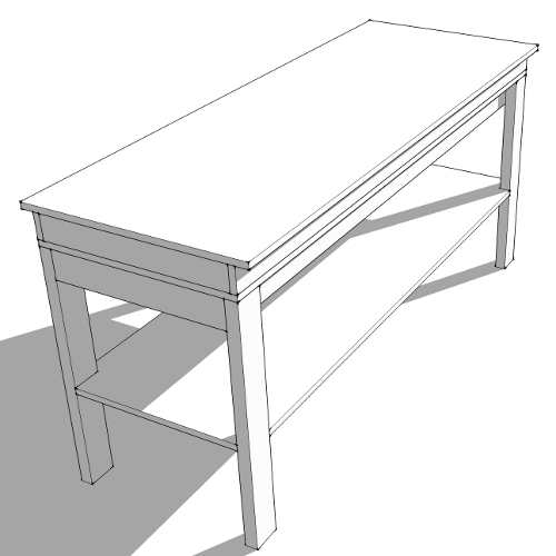
This is the table fully assembled. the talbe consists of standard 2x4 studs for
legs and frame. The middle shelf is used for storage and stability. More structure
underneath will stiffen the overall structure. just above the base is the torsion
box structure and table top.
An exploded view of all table parts.
Table legs and frame.
Shelf
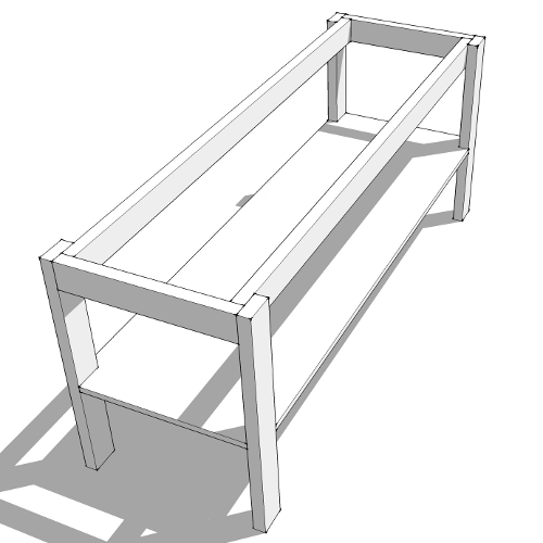
Shelf and frame together.
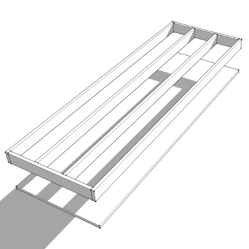
Torsion box - bottom layer and initial long ribbing.
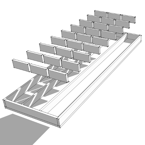
Lateral pieces to complete the grid.
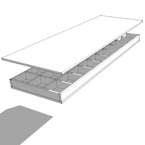
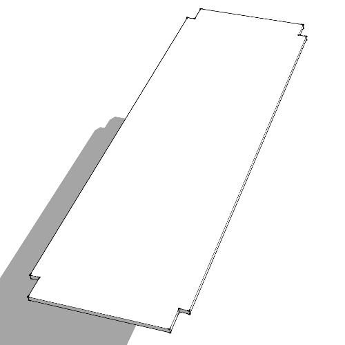
The top layer.
Packing List:
- List of Birch or MDO (Medium Density Overlay) pieces:
- Top and Bottom Gantry Box (2)
- Back Gantry Box (1)
- Z-Axis Motor Mount (1)
- Gantry Sides (2)
- Y-Axis Rail Support Top and Bottom (2)
- Y-Axis Rail Support Reinforcement (1)
- Z/Y Plate (1)
- Z-Axis Rail Supports (2)
- Z-Axis Middle Supports (4, 2 long and 2 short)
- Router/Spindle mounts (2)
- Vacuum Mount Bottom (2 Parts for Suction Enclosure)
- Vacuum Mount Top and Lead Screw Bearing Mount (1)
- Z-Axis Lead Screw and Bearing Mount (1)
- Y-Axis Chain Mount (4 - 1 long and 1 short and their respective clamps)
- Y-Axis Motor Mount (1)
- X-Axis Chain Mounts ((16 - Assemblies that are affixed to the table corners)
- Hardware List:
- Screws (#8) @ 1 1/4" (24)
- Screws (1/4") @:
- 1" (16)
- 1-1/2" (77)
- 2" (40)
- 2-1/2" (4)
- 3" (14)
- 3-1/2" (4)
- Screws (3/8") @:
- Nuts:
- #8 (18)
- 1/4" (46)
- Cross dowels (114)
- 3/8" (28)
- Eye Bolts (3)
- Hose Clamps (3)
- Washers:
- For #8 Screws (16)
- For 3/8":
- Small L-Brackets (For Anti-Backlash Nut) (2)
- Bearings:
- "V" Groove (3/8" Inside Diameter) (16)
- Standard with 1/2" Inside Diameter
for Lead Screws (2)
- 1/4 Inside Diameter for X-axis Motor shaft Ends (2)
- Couplings:
- 1/4" to 1/2" (1)
- 1/4" to 1/4" Rigid For X-Axis Shafts (2)
- Steel Collars (1/2" Inside Diameter): (1)
- Z-axis 10.5" lead screw (1)
- Anti-backlash nut (1)
- Drive Sprockets #25 9 teeth (3)
- Idler Sprockets #25 25 Teeth (5)
- Roller Chain #25 - Length show extra chain provided for convenience
- 8 Feet for X-Axis (2)
- 4 feet for Y-Axis (1)
- Rods at 1/4" Diameter and 14" in Length (2)
- Rails (aluminum angles drilled and cut to length) for the X, Y and Z axes
- Electronics:
- Stepping Motors at 425 oz-in NEMA 24 (3) - note NEMA 24 is a 60 mm Frame Size
- Motor Drivers at 3.0 amps Max Rating and 1/64 Microstepping (3)
- Power Supply 36v-8.8amp (1)
- Power Supply 5v (2)
- Breakout Board for
Computer Interface (1)
- Optional Table
- 1/4 - 1.5" Screws (70)
- Cross dowels (70)
- Birch or MDO Pieces for:
- Table Surface (4)
- Ends (4)
- Under Surface Structure (14)