
Price Options Your Cart
2" Strip Brush per inch (Backordered)
2" Flexible Strip Brush (Great for making dust shoes for the router or spindle)Strip Brushes are really useful for aiding in the capture of dust and chips being ejected from the milling process on the CNC machine (the router or spindle cutting process). The dust shoe that can be found on most of our CNC machines uses this strip brush. The strip brush encloses the cutting area and the vacuum creating an area of negative pressure, so the chips or dust will be carried directly to the vacuum end. The strip brush also serves as a wall or barrier that the chips will hit rather than getting ejected into the air. Just make a groove the same width of the rubber side of the brush and glue the brush in.
Click here for more information on this product.
----
Instructions for the Z-Axis Assembly for the blackToe and blackFoot CNC Machine
Kits:
These instructions are a replacement for the video instructions on how to assemble
the Z-axis assembly and router/spindle mount. The updated Z-axis Assembly includes
mounts for varying sizes compatible with the Porter Cable 890, 7518, and a 2.2 kW
spindle with a dust shoe.
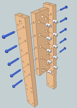 Parts
needed: Two long pieces on the sides (z-axis rail support side), one middle z-axis
rail support (long), 10 cross dowels and 10 screws at 1/4" x 1-1/2". The two z-axis
rail support sides will sandwich the wider piece in the middle. Leave the screws
loosened.
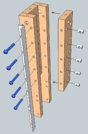 Parts needed:
Z-axis rail (the rail that matches the hole positions and orientation shown in the
illustration), one middle z-axis rail support (long), 5 cross dowels and 5 screws
at 1/4" x 1-1/2". With the rail positioned on the z-axis side rail support, add
the cross dowels and loosely fasten the screws into the cross dowels as shown in
the illustration.
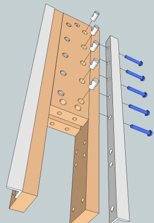 Parts needed:
Z-axis rail (the rail that matches the hole positions and orientation shown in the
illustration), one middle z-axis rail support (long), 5 cross dowels and 5 screws
at 1/4" x 1-1/2". Repeated step for other side of the z-axis. Leave the screws loosened.
For the spindle z-axis kit, the middle z-axis rail support will look very similar
to the part that is positioned just below. To properly identify this part, there
will be 9 holes on the face of the part.
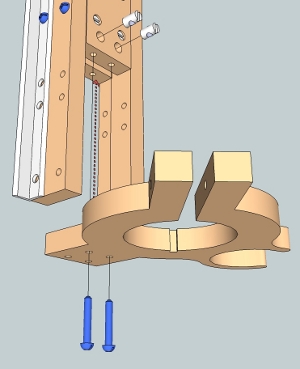 Parts needed: Top router mount, 2 cross dowels and 2 screws at 1/4" x 1-1/2". Fasten
the top router mount with the two screws and cross dowels as shown in the illustration.
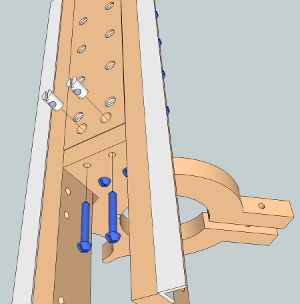 Parts needed: 2 cross dowels and 2 screws at 1/4" x 1-1/2". Fasten the back portion
of the top router mount with the two screws and cross dowels as shown in the illustration.
Fully tighten these four screws as there will be no access to these screws in later
steps.
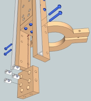 Parts needed: Middle rail support (medium length), 4 cross dowels and 4 screws at
1/4" x 1-1/2". Fasten the middle rail support along the back of the z-axis assembly
as shown in the illustration.
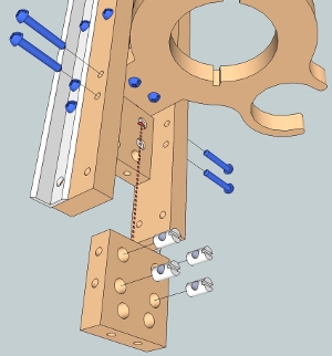 Parts needed: Middle rail support (medium length), 4 cross dowels and 4 screws at
1/4" x 1-1/2". Fasten the middle rail support along the front of the z-axis assembly
as shown in the illustration.
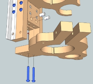 Parts needed: Bottom Router Mount, 2 cross dowels and 2 screws at 1/4" x 1-1/2".
Fasten the bottom router mount using the two front holes of the router mount as
shown inthe illustration.
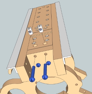 Parts needed: 2 cross dowels and 2 screws at 1/4" x 1-1/2". Fasten the back portion
of the bottom router mount as shown in the illustration. Fully tighten these four
screws as there will be no access to these screws in later steps.
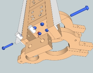 Parts needed: Middle z-axis rail support (short), 2 cross dowels and 2 screws at
1/4" x 1-1/2". Position the middle z-axis rail support and fasten this part with
the screws and cross dowels as shown in the illustration for the back of the z-axis
assembly.
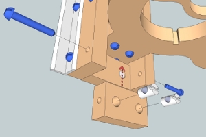 Parts needed: Middle z-axis rail support (short), 2 cross dowels and 2 screws at
1/4" x 1-1/2". Position the middle z-axis rail support and fasten this part with
the screws and cross dowels as shown in the illustration for the front of the z-axis
assembly. At this point of the assembly, lay the entire assembly on a flat table
oriented so that the rails are against the table. Tighten all of the loose screws
making sure that the assembly stays flat on the table. This will insure that the
rails are as parallel to each other as possible.
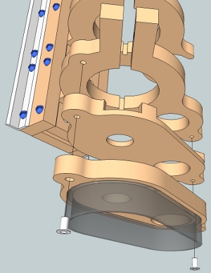 Parts needed: Top and bottom dust shoe and 2 nut inserts 1/4". Drive in the nut
inserts into the dust shoe that contains the brush using an allen wrench. Position
the dust shoe parts as shown in the illustration in preparation for the next step.
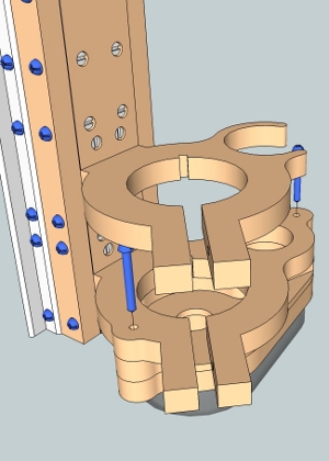 Parts needed: 2 screws at 1/4" x 2". Insert the screws at the top of the bottom
router mountand tighten the screws into the nut inserts. A short or angled screws
driver will be needed for one tightening one of these screws.
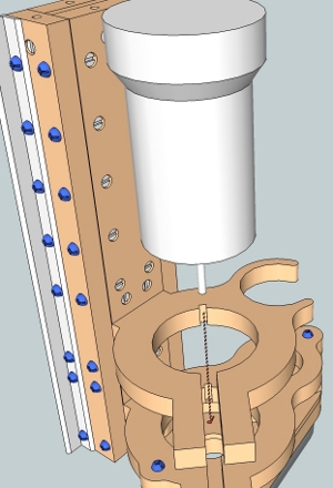 Parts needed: Router or spindle. This step can be done after the machine is completely
assembled. Slide the router or spindle through the openings of the router mounts.
If the routers contain dimples on the side, orient the router so that the dimple
is aligned with the notch in the router mount. Ant obstructions fastened to the
side of the router will need to be removed prior to installing the router to the
z-axis assembly.
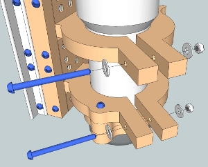 Parts needed: 2 screws at 1/4" x 3", 4 washers 1/4" and 2 nuts 1/4". These components
are used to firmly squeeze the router mounts rount the housing of the router. Gently
tighten the screws until the router is secure.