[ Log In ]
[ Register ]

Question #: 9020

Question: how to wire limit switches

Current Solution

The parallel breakout board allows for 4 input connections. Each input connection can have an unlimited number of switches, but if you need to separate the switch circuit for, say, all of the home switches, you can use another input pin. There is no need to add another breakout board to add more switches unless you need to use the input pins for totally unique conditions that may or may not be related to CNC functions.

Customer response:
To Clarify: I need to set up 3 home switches which can double for limits (that's 3 pins.). Another pin for a probe. That's 4 pins used. Now I need to set up the other limit and E-stop switches. No pins left, how do I do that? Can a ground pin be doubled up on?

Plus, I have a SuperPID. Another pin?

Additional answer:
You can put all of your limit switches (including the E-stop which serves the same purpose as the limit switches) and home switches on a single pin. When homing, mach3 will move the axis it wants to home, hit the switch, pull away from the switch, then move the next axis and repeat the steps for the next two axes.

The probe is on the 2nd pin. The SuperPID is on the 3rd pin and now you have another pin remaining.

The GND terminal can be doubled up.

Additional Information:
how about a diagram to reference showing the pin-out to use

Here is the diagram for the parallel breakout board (pins 10 through 13 are used for input):

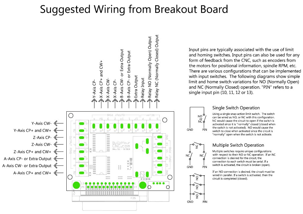
The circuit is from the GND to the input

Here is the diagram for the Mach3 USB board (pins I1 through I4 are used for input):
https://www.buildyourcnc.com/Documents/Electric%20Wiring%20Diagram.pdf
The circuit is from the V- to the input pin

Respond:

Other Possible Solutions to this Question

  • MY LIMIT SWITCHES ARE TRIGGERING AT RANDOM.

    Are you using shielded wire? If so, take the shield to ground. If there are any other wires in the cable that is not being used, ground those as well. The customer can also try moving the cables as far away as possible from the motor wires and motors.

    Additional Information:


    Additional Information:

    Click the link to add information to this solution:
    MY LIMIT SWITCHES ARE TRIGGERING AT RANDOM.

  • HOW DO I SET THE DIP SWITCHES?

    blueChick:

    X-axis
    “CW230 (3.0A) Driver”
    Set to 1/16 Microstep, 2.7A
    Dipswitches: 11001100
    Mach3 Motor Tuning: 1422.22 steps/in

    Y-axis
    “CW230 (3.0A) Driver”
    Set to 1/16 Microstep, 2.7A
    Dipswitches: 11001100
    Mach3 Motor Tuning: 1422.22 steps/in

    Z-axis
    “CW230 (3.0A) Driver”
    Set to 1/4 Microstep, 2.7A
    Dipswitches: 10101100
    Mach3 Motor Tuning: 1600 steps/in

    blackToe:

    X-axis
    “CW230 (3.0A) Driver”
    Set to 1/16 Microstep, 2.7A
    Dipswitches: 11001100
    Mach3 Motor Tuning: 1422.22 steps/in

    Y-axis
    “CW230 (3.0A) Driver”
    Set to 1/16 Microstep, 2.7A
    Dipswitches: 11001100
    Mach3 Motor Tuning: 1422.22 steps/in

    Z-axis
    “CW230 (3.0A) Driver”
    Set to 1/4 Microstep, 2.7A
    Dipswitches: 10101100
    Mach3 Motor Tuning: 1600 steps/in

    blackFoot:

    X-axis
    “CW8060 (6.0A) Driver”
    Set to 1/16 Microstep, 2.7A
    Dipswitches: 11001100 (“0”=down, “1”=up)
    Mach3 Motor Tuning: 914.29 steps/in

    Y-axis
    “CW230 (3.0A) Driver”
    Set to 1/16 Microstep, 2.7A
    Dipswitches: 11001100
    Mach3 Motor Tuning: 1422.22 steps/in

    Z-axis
    “CW230 (3.0A) Driver”
    Set to 1/4 Microstep, 2.7A
    Dipswitches: 10101100
    Mach3 Motor Tuning: 1600 steps/in

    greenBull:

    X-axis
    “CW8060 (6.0A) Driver”
    Set to 5.43A, 1/16 Microstep
    Dipswitches: 01100110 (“0”=down, “1”=up)
    Mach3 Motor Tuning: 914.29 steps/in

    Y-axis
    “CW8060 (6.0A) Driver”
    Set to 5.43A, 1/16 Microstep
    Dipswitches: 01100110
    Mach3 Motor Tuning: 914.29 steps/in

    Z-axis
    “CW8060 (6.0A) Driver”
    Set to 5.43A, 1/4 Microstep
    Dipswitches: 01100100
    Mach3 Motor Tuning: 1600 steps/in

    Additional Information:

    Click the link to add information to this solution:
    HOW DO I SET THE DIP SWITCHES?

  • LIMIT SWITCHES FOR AXIS. THE PRINT SHOWS THAT YOU CAN WIRE LIMITS EITHER N.O. OR N.C. SO IF THIS IS CORRECT I WOULD NEED TO TELL BOARD IN SOFTWARE HOW LOOK AT THESE LIMITS, I'M GOING GET AN INPUT LOOSE DEPEND ON IT.

    BYCNC Response:
    This is correct. You will need to use a method appropriate for the software you are using. Also remember that NC switches are typically wired in series, while NO switches are normally wired in parallel.

    User Response:
    I am using the cnc planet software for your USB board. Are the limit configurations in this software?

    BYCNC Response:
    Yes, Planet CNC software is compatible with the use of limit switches. Configuration information will depend on your specific application. You can view Planet CNC's information here: http://www.planet-cnc.com/files/CNCUSBController.pdf

    Click the link to add information to this solution:
    LIMIT SWITCHES FOR AXIS. THE PRINT SHOWS THAT YOU CAN WIRE LIMITS EITHER N.O. OR N.C. SO IF THIS IS CORRECT I WOULD NEED TO TELL BOARD IN SOFTWARE HOW LOOK AT THESE LIMITS, I'M GOING GET AN INPUT LOOSE DEPEND ON IT.

  • I HAVE A 2000 WK 11–3 Z LIMIT SWITCHES GOING TO C10R10 BREAKOUT BOARD . CAN ALSO USE THEM AS MY HOME POSITION WELL. NEED THE WIRING CONFIGURATION

    No, you should not have received two parallel breakout boards in your CNC kit. You can return the extra item using standard shipping with COD. Our apologies for the confusion and the inconvenience.

    I will answer the other question as another FAQ. Please check the Customer Service page to see the answer to that question.

    If you have difficulty finding the answer, here is a link:
    https://www.buildyourcnc.com/FAQ/13636

    Click the link to add information to this solution:
    I HAVE A 2000 WK 11–3 Z LIMIT SWITCHES GOING TO C10R10 BREAKOUT BOARD . CAN ALSO USE THEM AS MY HOME POSITION WELL. NEED THE WIRING CONFIGURATION

  • HOW DO I WIRE FROM THE BREAKOUT BOARD TO DRIVER?

    CP+ to COM
    CP- to STEP
    CP+ to CW+ (small jumper wire)
    CW- to DIR

    Additional Information:
    If the driver does not have CP or CW labels, the CP is Step and the CW is Direction or DIR. If you connect the 5v to CP+ (or Step+) and CW+ (or DIR+) and the pin to CP- (or Step-) and another pin to CW- (or DIR-), then in software, the configuration for the step on that axis must be active low. Otherwise, if you connect the GND to CP- (or Step-) and CW- (or DIR-) and the pin to CP+ (or Step+) and another pin to CW+ (or DIR+), then in software, the configuration for the step on that axis must be active high.

    Additional Information:
    If you have a driver that is labeled pul, dir and ena: Pul+ is the Step+ and Pul- is the Step-. Pul is short for pulse. A pulse will create a step. Don't worry about the enable terminals.

    On the x-axis, pin #2 can go to pul- and pin #3 can go to dir-. The 5v will go to pul+ and dir+. The configuration for each axis for step will be active low and toggle active low for the dir on each axis to make it go in the direction desired.

    Additional Information:


    Additional Information:


    Additional Information:


    Additional Information:

    Click the link to add information to this solution:
    HOW DO I WIRE FROM THE BREAKOUT BOARD TO DRIVER?

  • HOW LONG FOR ME TO BUILD IT?

    The length of time it will take to build a CNC machine kit is not an easy answer. There may be a wide array of circumstances that limit a persons abilities to build the cnc machine kit in an efficient timeframe; however, if you have moderate dexterity and moderately mechanically inclined, you should have no problem building one of our machines within one weekend if the project has very little downtime.

    Additional Information:

    Click the link to add information to this solution:
    HOW LONG FOR ME TO BUILD IT?

  • HOW LONG DOES IT TAKE TO SHIP

    Unfortunately I am not able to give an estimate of shipping time. This is because there are multiple shipping options, Some of them cost more than others, but ensure the package arrives in a certain number of days. Others do not give a number of days, and many factors could change the length of shipping time, such as weather, or busy season. It would be best to choose an option you are comfortable with the price of, and then Google search the typical times it takes for that option to get to you, or call the shipping company and request that estimated time from them.

    Additional Information:

    Click the link to add information to this solution:
    HOW LONG DOES IT TAKE TO SHIP

  • HOW TO CONNECT THE INVERTER WALL?

    Input to VFD:
    240V Active - R
    240V Neutral - S
    Ground - E

    Additional Information:

    Click the link to add information to this solution:
    HOW TO CONNECT THE INVERTER WALL?

  • LIMIT SWOTCXH PROBLEM

    This is a common problem. Are you using shielded wire? If so, take the shield to ground. If there are any other wires in the cable that is not being used, ground those as well. Also try moving the cables as far away as possible from the motor wires and motors.

    Click the link to add information to this solution:
    LIMIT SWOTCXH PROBLEM

  • LIMIT SWITCH PROBLEM

    This is a common problem. Are you using shielded wire? If so, take the shield to ground. If there are any other wires in the cable that is not being used, ground those as well. Also try moving the cables as far away as possible from the motor wires and motors.

    Click the link to add information to this solution:
    LIMIT SWITCH PROBLEM

  • HOW TO CONNECT THE SPINDLE INVERTER?

    U - Pin1
    V - Pin2
    W - Pin3
    Pin4 Dead

    Additional Information:
    My home made cnc is a big problem with my NC connection. When in start my spindle it will be gone wrong. It will be limith switch problem anytime. Need help thanks.

    Additional Information:


    Additional Information:


    Additional Information:


    Additional Information:


    Additional Information:


    Additional Information:


    Additional Information:


    Additional Information:


    Additional Information:


    Additional Information:


    Additional Information:


    Additional Information:


    Additional Information:


    Additional Information:


    Additional Information:


    Additional Information:

    Click the link to add information to this solution:
    HOW TO CONNECT THE SPINDLE INVERTER?

  • HOW DO YOU HOOK UP THE VFD TO SPINDLE?

    U - Pin1
    V - Pin2
    W - Pin3
    Pin4 Dead

    Additional Information:
    My home made cnc is a big problem with my NC connection. When in start my spindle it will be gone wrong. It will be limith switch problem anytime. Need help thanks.

    Additional Information:


    Additional Information:


    Additional Information:


    Additional Information:


    Additional Information:


    Additional Information:


    Additional Information:


    Additional Information:


    Additional Information:


    Additional Information:


    Additional Information:


    Additional Information:


    Additional Information:


    Additional Information:


    Additional Information:


    Additional Information:

    Click the link to add information to this solution:
    HOW DO YOU HOOK UP THE VFD TO SPINDLE?

  • HOW DO YOU CONNECT THE INVERTER TO AC?

    Input to VFD:
    240V Active - R
    240V Neutral - S
    Ground - E

    Additional Information:

    Click the link to add information to this solution:
    HOW DO YOU CONNECT THE INVERTER TO AC?

  • HOW CAN MOUNT THE EXTRUDER TO WHITEANT

    Mounting the extruder to the whiteAnt can be done a couple of ways. One is to take the 4 mounting holes located at the lower portion of the z-axis rail support and use long screws protruding out. Take a thinner material and drill the four holes matching the locations of the 4 screws and screw on nuts to hold it in place. The other option would be to use the metal bracket and fasten to the edge of the rail support.

    Click the link to add information to this solution:
    HOW CAN MOUNT THE EXTRUDER TO WHITEANT

  • HOW TO COOL THE BLACKTOOTH 40W LASER TUBE

    Cooling is not as tricky as you might think. There is 3 ways to approach this, only 2 really matter for a low scale 40w setup. First one is the cheapest and easiest. The higher the temp of water the worse your performance will be, from what I understand anything in the 30C range is about the most tolerable it gets. Lower is better. But not frozen...from what I've been told a very experienced cutter, he found 8C was the highest power he achieved.

    1. Use a 5 Gallon resovoir system which gives you a fairly large space of water to heat up before you need to tend to it. Add about a cup of anti-freeze to the mix of DISTILLED water. You don't want ANY minerals in the water that might build up in your system. The anti-freeze works to keep algae and other ickies from growing in your water.

    2. Use a smaller resovoir system (or even closed loop) and install 1 or more radiators found in CPU cooling systems with 120mm fans attached. This will continously cool your water system to ambient room temperatures, but with a tiny resovoir it will be difficult to add things like ice-packs to drop the temps if the ambient is quite hot.

    3. Using an industrial coolant system. Overkill and unless your cutting A LOT, this is a very expensive option to take. You can also explore the idea of Peltier cooling but it is extremely expensive electricity/BTU wise compared to an industrial cooler.

    Click the link to add information to this solution:
    HOW TO COOL THE BLACKTOOTH 40W LASER TUBE

  • HOW TO CONTROL MY 2.2 KW SPINDLE VIA MACH3

    You can go to our instructions on for the breakout board here: http://www.buildyourcnc.com/item/electronicsAndMotors-parallel-breakout-relay to get the information on turning the spindle on and off from the computer and mach3. Alternatively, you can connect the computer using RS485 serial to the inverter and send control commands that way.

    Additional Information:
    HOW TO CONTROL MY 2.2 KW SPINDLE VIA MACH3 usb

    Additional Information:


    Additional Information:


    Additional Information:
    How should I wire the Mach3 card (red, 4 axis) and the vfd (Yl620-a)?

    Additional Information:


    Additional Information:


    Additional Information:

    Click the link to add information to this solution:
    HOW TO CONTROL MY 2.2 KW SPINDLE VIA MACH3

  • HOW DO YOU HOOK UP THE SPINDLE TO INVERTER?

    U - Pin1
    V - Pin2
    W - Pin3
    Pin4 Dead

    Additional Information:
    My home made cnc is a big problem with my NC connection. When in start my spindle it will be gone wrong. It will be limith switch problem anytime. Need help thanks.

    Additional Information:


    Additional Information:


    Additional Information:


    Additional Information:


    Additional Information:


    Additional Information:


    Additional Information:


    Additional Information:


    Additional Information:


    Additional Information:


    Additional Information:


    Additional Information:


    Additional Information:


    Additional Information:


    Additional Information:


    Additional Information:

    Click the link to add information to this solution:
    HOW DO YOU HOOK UP THE SPINDLE TO INVERTER?

  • HOW DIFFICULT IS IT TO BUILD THE BLACKTOOTH

    The blackTooth Laser cutter and Engraver can be built in a weekend. Take a look at the build instructions and try to determine if you feel you have sufficient capability to put together the laser system.

    Click the link to add information to this solution:
    HOW DIFFICULT IS IT TO BUILD THE BLACKTOOTH

  • HOW THE ROUTER IS CONNECTED TO ELECTRONICS?

    The parallel breakout board has a relay that can turn the router on and off according to the control software in the computer. The router will turn on automatically prior to the machine moving (a time frame can be set so the router is up to speed). When the machine is finished and is not moving, the router automatically turns off. This is with the m3, m4, and m5 codes in the g-code.

    If you are interested in the USB breakout board, you will need to get an independent relay board.

    Click the link to add information to this solution:
    HOW THE ROUTER IS CONNECTED TO ELECTRONICS?

Get Help with:
This Product
Orders
Tech Support
Sales
This Product
Order Query
Tech Support
Sales
Not logged in. Log In Register
Track Order(s)
View Order(s)
I Want to Schecule a One-On-One Paid Tech Support Session
Book an Appointment Pertaining to a BuildYourCNC Product (Free)
Ask a Quesion Below (Free):
Book an Appointment Pertaining Other Equipment ($60/half hour)
Book an Immedite Appointment Pertaining Other Equipment ($120/half hour)
Ask a Quesion Below (Free):
Waiting for response... I may not answer immediately, but I was notified on my cellular phone so my response is forthcoming. If I don't respond immediately, you can always go to the [My Account] page to see all of our chats at any time.