Practical CNC Joinery Part 2 - Complex Jigsaw Miter Flat Joint
Share
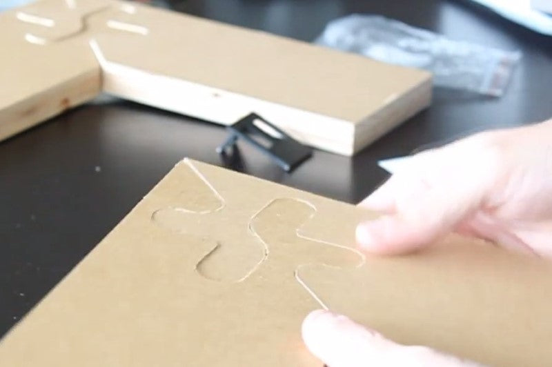
In this video we’ll be showing you how to make a complex jigsaw miter flat joint. We aimed to make it a little fancier than the standard joint, but that presented some challenges. The amount of material matters because of the vibrations, and there was a bit of a sawtooth issue. Getting the depth perfectly right is also an issue, so on this particular joint you want to make sure the half depth perfect, with a spoilboard that is perfectly flat and surfaced. We start out with four inch pieces of wood, just like last time, but in a flat arrangement. First we make the design a bit longer (offset by four) so it looks like a frame, and mirrored at a right angle. For a more complex type of joint, we just want to take a line and move it around and meet back at the other corner. You want to make sure there are enough corners around that allowed it to be locked in place. This is further illustrated in the video. With the regular type of joint, you’d be able to lock it in place, but not tear it apart. From here you’d need to consider the size of bit you will be using. In the video we’re using ¼” so you’d need to make the radius of all the corners 1/8th of an inch. Now you have a general joint. However, there are a couple problems with this joint. If you draw the lines you will see that the joint crosses a boundary you don’t want it to. You want it to work within the square. There are a lot of designs that can be created to add attractive features to the corner of the wood. We place the lines inside to make sure we know where our boundaries are. Once the design has been prepped, the corners need to be rounded for the size of the bit (1/8th inch). Once completed, we can see there is a little bit of a room, and the end mill would have to get through the area, cut out, and then leave material behind. The piece also looks brittle like it could break easily, so we need to increase the radius of the curves. Now the joint looks like it will be useable and does not go outside of the boundary. From here we create two pieces from the first one. After both are generated, we’re going to only pocket the first piece halfway through the wood, the other will be halfway through the other side. This way all material can be removed halfway through the wood, so everything will be able to marry itself very easily into the other portion. In the last video (part one), we used a zero tolerance between the fingers. In this case, we want to create more space between the puzzles pieces because of the nature of the geometry. Tolerances are put in to make sure the pieces will fit snugly. We will use .01” of an inch. After looking at the tolerances, we realized we needed to readjust some of the lines. Once mirrored, we can see the small amount of difference between the two pieces when put on top of each other. Next we used the BO command to put a polygon to make sure there is a nice corner around the edge. This creates a polygon boundary. We then rounded off the corners using circles. We needed to make sure it will pocket the pieces correctly we polygon boundaries. For this we used an offset of .25. After pocketing, we will cut out the square and replace it with a rectangle. From here we are now able to save the file and open it in CAMBAM. Inside CAMBAM, after loading the file, we create the pocket for the first piece. We select the polygon and use the pocket machining operation. Next we need to figure out the target depth. At this point you need to measure the actual thickness of the wood you’ll be using. Our piece is .76 so our target depth is .38. After setting the target depth we did an inside profile (a finishing profile) to do a roughing pass in order to make it nice and precise. Also make sure the profile is .38. There should be 2 outside profiles. One for finishing and one for roughing. Again, you’ll want to watch the video for more precise instructions on everything that is being done. After completing the design, we are ready to produce g-code and run the machine! You will notice that we’re using the greenLean vertical for this particular cut. After the pieces finished, we discovered we didn’t quite make enough of a tolerance between the two, so we had to adjust the tolerance a little bit to make sure they locked into place perfectly. After the adjustment you will see the two pieces were able to fit after an adjustment of .02.
