Instructions
1

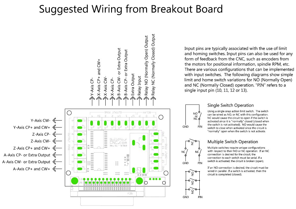
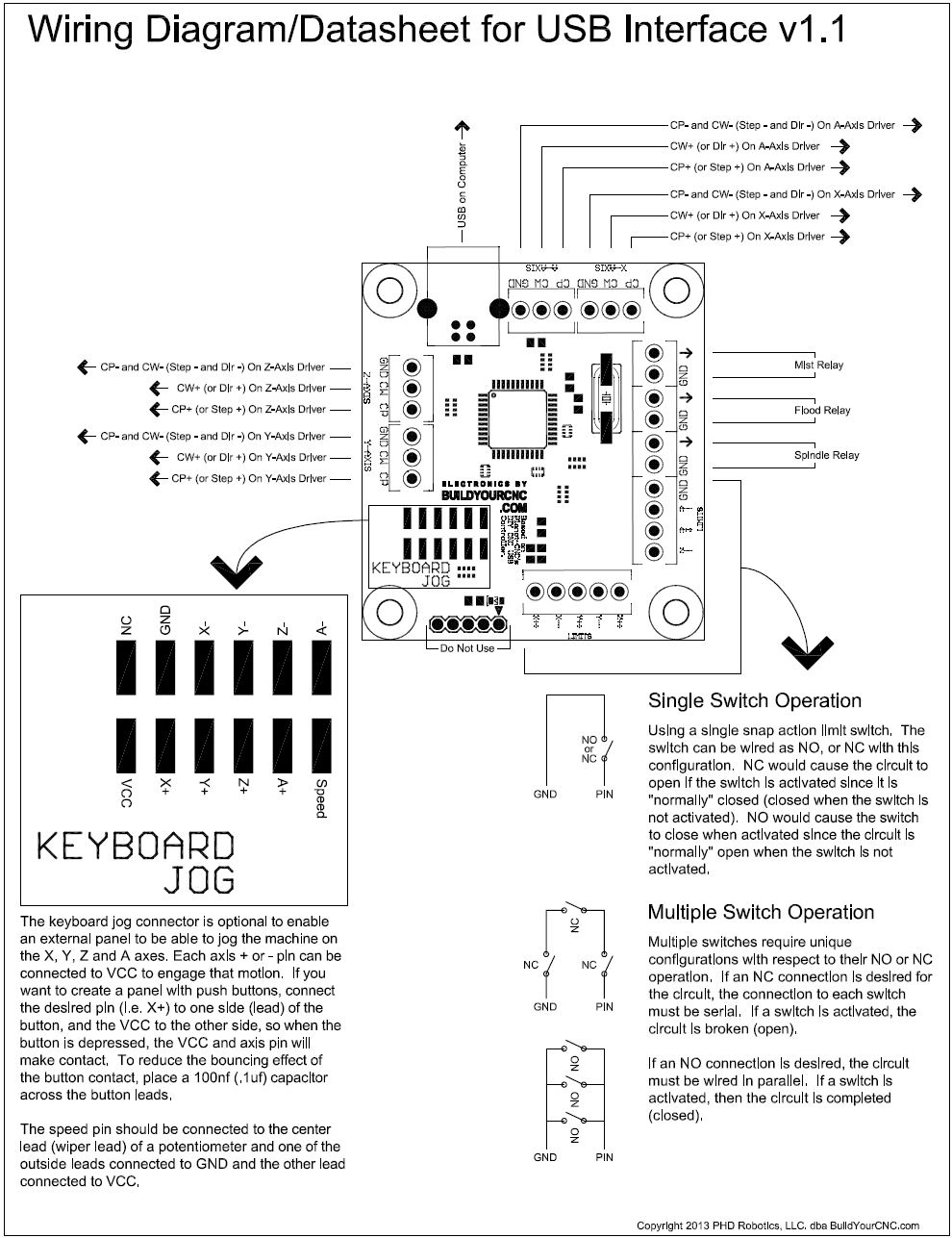
Wiring Diagrams and Tutorials: Parallel Breakout Board: Diagram | Video Tutorial USB Breakout Board: Diagram | Video Tutorial 2.2KW Spindle: Wiring Instructions (Scroll down to Instructions)
2

Should be as short as possible to be able to reach the top/middle of the machine bed.
3

Minimum clearance for the top layer overhang is 2 inches to allow for chain mount space.
4

Any obstruction under the top layer of the table should be a minimum of four (4) inches. This will allow for the lower part of the gantry side clearance.
5

The strict width of the table shall be 51-7/8 inches. You have about 1/4 inch of flexibility wider, but not narrower than 51-7/8 inches. The length of the table for 8 feet of long axis travel is 120 inches. This compensates for the bearing spacing on the gantry sides. If a longer travel is desired, just increase this dimension.
6

Insert one 1/2 inch ID bearing to the left gantry side.
7

Add the idler sprocket assembly to left gantry side using one 3/8 x 2 inch screw, two 3/8 inch medium washers, one 3/8 inch thin washer and one 3/8 inch nut.
8

Insert the v-groove bearing and idler sprocket assembly to the left gantry side using one 3/8 x 3 inch screw, two 3/8 inch large washers, two 3/8 inch thin washers one v-groove bearing, one idler sprocket and one 3/8 inch nut.
9

Insert one 1/4 x 1-1/2 inch screw and cross dowel to serve as the bearing adjustment screw.
10

Install the lower v-groove bearing assembly to the left gantry side as shown. Use one 3/8 x 2 inch screw, one v-groove bearing, one 3/8 inch thin washer, two 3/8 inch large washers and one 3/8 inch nut.
11

Add a v-groove bearing assembly to the upper front portion of the left gantry side using one 3/8 x 2 inch screw, two large 3/8 inch washers, one 3/8 inch thin washer and one 3/8 inch nut.
12

Add the lower front v-groove bearing adjustment screw to the left gantry side using one 1/4 x 1-1/2 inch screw and cross dowel nut.
13

Add the lower front v-groove bearing assembly to the left gantry side using one 3/8 x 2 inch screw, one v-groove bearing, one 3/8 inch thin washer, two 3/8 inch large washers and one 3/8 inch nut.
14

Orient and arrange the left gantry side and gantry front as shown. Pay close attention to the orientation of these two parts.
15

Fasten the left gantry side with the gantry front using two 1/4 x 1-1/2 inch screws and cross dowels.
16

Continue the fastening of the left gantry side with the gantry front with one 1/4 x 1-1/2 inch screw and a cross dowel.
17

Insert one 1/2 inch ID bearing into the right gantry side as shown.
18

Add the idler sprocket assembly to the right gantry side using one 3/8 x 2 inch screw, one 3/8 inch nut, two 3/8 inch large washers, one 3/8 inch thin washer and one idler sprocket.
19

Add the v-groove bearing and idler sprocket assembly to the right gantry side using one 3/8 x 3 inch screw, one v-groove bearing, two 3/8 in thin washers, two 3/8 inch large washers, one idler sprocket and one nut.
20

Add the lower v-groove bearing adjustment screw to the right gantry side using one 1/4 x 1-1/2 inch screw and cross dowel.
21

Add the lower read v-groove assembly to the right gantry side using one 3/8 x 2 inch screw, one v-groove bearing, one 3/8 inch thin washer, two 3/8 inch large washers, and one 3/8 inch nut.
22

Add the front lower v-groove adjustment screw to the right gantry side using one 1/4 x 1-1/25 inch screw and cross dowel.
23

Add the lower front v-groove bearing to the right gantry side using one 3/8 x 2 inch screw, one 3/8 inch thin washer, two 3/8 inch large washers and one 3/8 inch nut.
24

Add the upper front v-groove bearing assembly to the right gantry side using one 3/8 x 2 inch screw, one 3/8 inch thin washer, two 3/8 inch large washers and one 3/8 inch nut.
25

Arrange and orient the right gantry side and gantry front as shown.
26

Fasten together the right gantry side and gantry front using two 1/4 x 1-1/2 inch screws and cross dowels.
27

with one 1/4 x 1-1/2 inch screw and cross dowel, continue fastening the right gantry side to the gantry front.
28

Fasten the upper y-axis rail to the rail support as shown. Pay close attention to the orientation of the rail and the y-axis rail support. Use 8 1/4 x 1 inch screws and cross dowels for this step. Make sure to keep the screws loosely fastened.
29

Fasten the lower y-axis rail to the y-axis rail support piece using eight 1/4 x 1 inch screws and cross dowels. Keep these screw loosely fastened until all of the screws are in. Completely tighten the screws while the rails and support piece is resting on a flat table as shown.
30

Arrange the y-axis rails and support piece with the Gantry Front as shown. Pay close attention to the orientation of the y-axis rail support. An easy way to determine orientation is the counter bored holes and the two upper holes on the ends of the y-axis rail support.
31

Fasten the y-axis rail support to the gantry front using eighteen (18) 1/4 x 1-1/2 inch screws and 1/4 inch nuts. It is best to insert all of the screws into all of the holes prior to adding the nuts. Start by inserting screws at the extreme ends of the y-axis rail support piece so the parts are held in place with less effort. After all of the screws are inserted, add the nuts and tighten.
32

Fasten the right gantry side to the y-axis rail support and right gantry side using two 1/4 x 2 inch screws and cross dowels.
33

Fasten the y-axis rail support to the left gantry side using two 1/4 x 2 inch screws and cross dowels.
34

Using two C-clamps, secure two of the x-axis rails above and below the table overhang. On this side, make sure the rails are flush with the table top. Make sure to align these rails so that the holes are perfectly aligned with both rails.
35

Drill the first hole through the table at one end of the rails.
36

Add one 1/4 x 1-1/2 inch screw and a nut to fasten this part of the X-Axis Rails. Remove the C-clamp when this screw and nut are fastened tightly.
37

Drill a hole at the other extreme of the x-axis rails.
38

Add one 1/4 x 1-1/2 inch screw and nut and tighten firmly around the x-axis rails. Remove the C-clamp after the screw and nut are tightened.
39

This is an important step to make sure the x-axis rail are as straight as possible. Add a C-Clamp to the midpoint of the x-axis rails and with another person, look down the length of the rails and adjust the C-Clamp and rails until the rails are straight and then tighten the clamp.
40

Drill a hole through the table next to the c-clamp.
41

Insert one 1/4 x 1-1/2 inch screw and nut at the midpoint of the rails and tighten firmly.
42

Drill the remaining holes for the x-axis rails keeping an eye on the straightness of the rails as these drills are made. Use extra c-clamps if further straightness is not maintained during the drilling process.
43

Secure the x-axis rails in the holes just drilled while always keeping an eye on the straightness of the rails.
44

Secure the second set of x-axis rails using two c-clamps (more if you feel necessary).
45

with two or more people to lift the gantry assembly, slide the gantry side bearings onto the x-axis rails. Notice where the c-clamps are located in this step. This will allow some flexibility in the second set x-axis rails. As the gantry is positioned and let rest, adjust the c-clamps to allow the rails to correct its position. Be very careful not to loosen the c-clamps too much as the rails will rotate out of position and the gantry can fall to one side.
46

Once the rails are correctly positioned, add another c-clamp to the end to secure the x-axis rails, behind the gantry. Make sure the gantry is as close to this position as possible so the rail will be at the best possible position with respect to the v-groove rails.
47

Move the gantry to the front of the table close to the c-clamp at that end and adjust the c-clamp to make sure the x-axis rail is in the correct position. Drill the first hole for this second set of x-axis rails.
48

Using one 1/4 - 1-1/2 inch screw, fasten the rails to the table at this end first making sure that the rails is at the best possible position.
49

Move the gantry to the other end of the table. Adjust the c-clamp if necessary and drill a hole through the table.
50

Fasten this end with one 1/4 -1-1/2 inch screw and nut.
51

Drill the hole next to the hole on the end making sure that the gantry bearing is very close to the drill area to insure that the rail will be at the correct position.
52

Fasten with on 1/4 x 1-1/2 inch screw and nut. Do the same drilling and fastening for the next hole.
53

For the fourth hole and remaining holes, drill and fasten each hole while keeping the gantry very close to the drilling area and fastening area. This will force the rail into the correct position in relation to the width of the gantry and the positions of the v-groove bearings.
54

55

Arrange and orient the gantry bottom to the gantry front. Pay close attention to the orientation of the gantry bottom and where the small hole near the middle is located.
56

Fasten the gantry bottom to the gantry front using nine 1/4 x 1-1/2 inch screws and cross dowels. Keep these screws loosely fastened until all of the screws and cross dowels are in.
57

Position the gantry top as shown paying close attention to the orientation.
58

Fasten the gantry top to the gantry front as shown using nine 1/4 x 2 inch screws and cross dowels. Keep these fasteners loosely fastened until all of the screws and cross dowels are in.
59

Insert the x-axis motors into position where the screw holes in the gantry top and gantry front is located. The screw hole in the gantry bottom will not be used.
60

Insert the cross dowel as shown.
61

Insert one 1/4 x 2 inch screw and loosely drive the screw into the cross dowel.
62

Fasten the top of the X-axis stepper motor mount using one 1/4 1-1/2 inch screw and cross dowel as shown.
63

Slide one rigid coupling (coupler) into one 1/2 inch rod. Position the rigid coupling past the end of the rod as shown.
64

Insert the other end of the rod through the 1/2 inch bearing that is seated into the left gantry side.
65

Insert one rigid coupling onto the other 1/2 inch rod as shown.
66

Insert rod into the 1/2 inch bearing located in the right gantry side as shown.
67

Fasten motor onto the motor mount as shown using four 1/4 x 1-1/2 inch screw and 1/4 inch nuts. Make sure the wires from the motor is positioned at the top of the motor.
68

Slide both rigid coupling so that the coupling equally cover the stepper motor shaft and the rod (rod half was through the coupling and the motor shaft half way through the coupling).
69

Slide the drive sprocket onto the rod protruding from the left gantry side. Orient as shown so that the drive sprocket can be aligned with the idler sprockets below. Tighten the set screws when the proper alignment is achieved. Do this on the rod protruding out of the right gantry side as well.
70

Fasten the chain mount to the bottom chain mount support using three 1/4 x 1-1/2 inch screws and cross dowels. Keep these loosely fastened.
71

Fasten top chain mount support to the chain mount as shown using two 1/4 x 1-1/2 inch screws and cross dowels. Keep these loosely fastened.
72

Slide the chain mount assembly onto the table overhang as shown. Squeeze the top and bottom chain mount supports against the overhang and tighten all of the screws.
73

Bring the gantry close to the mount and align the mount laterally to center the sprocket teeth to the midpoint of the slot opening in the chain mount. Drill three holes to prepare this mount for fastening to the table.
74

Fasten the chain mount to the table using three 1/4 x 3 inch screws and 1/4 inch nuts.
75

Insert one eyebolt, 1/4 inch washer and 1/4 inch nut as shown. Repeat all of the steps of assembling the chain mount assembly and fastening them to the table. For the right side of the table, flip the assembly parts so that they will extend off of the right side of the table.
76

Route the x-axis roller chain as shown. To ease this process, first drape the roller chain over the drive sprocket. Then bring each end of the roller chain to the mount making sure that the roller chain routes under the idler sprockets. Repeat this process on the right side of the table.
77

Fasten each roller chain end as shown using two #4 screws and #4 nuts. The #4 screws will fit between the pins and plates of the roller chain link. Repeat this process for each corner of the table (each end of the two x-axis roller chains).
78

Attach the z-axis upper right v-groove bearing adjustment screw to the z/y plate as shown using one 1/4 x 1-1/2 inch screw and cross dowel. Pay close attention to the orientation of the z/y plate.
79

Attach the z-axis upper right v-groove bearing assembly to the z/y plate using one 3/8 x 2 inch screw, two 3/8 inch large washers, one 3/8 inch thin washer, one v-groove bearing, and one 3/8 inch nut.
80

Attach Upper right y-axis v-groove bearing adjustment screw using one 1/4 x 1-1/2 inch screw and cross dowel.
81

Attach upper right v-groove bearing assembly using 3/8 x 2 inch screw, one v-groove bearing, one 3/8 inch thin washer, three 3/8 inch large washers, and one 3/8 inch nut.
82

Attach lower right Y-axis v-groove bearing assembly using one 3/8 x 2 inch screw, one v-groove bearing, one 3/8 inch thin washer, two 3/8 inch large washers and one 3/8 inch nut.
83

Attach the lower right z-axis v-groove adjustment screw using one 1/4 x 1-1/2 inch screw and cross dowel.
84

Attach the lower right z-axis v-groove bearing assembly using one 3/8 x 2 inch screw, two 3/8 inch large washers, one 3/8 inch thin washer, one v-groove bearing and one 3/8 inch nut.
85

Attach the lower left z-axis and y-axis v-groove bearing assembly using one 3/8 x 3 inch screw, two v-groove bearing, two 3/8 inch thin washer, three 3/8 inch large washers and one 3/8 inch nut.
86

Attach the upper left y-axis v-groove bearing adjustment screw using one 1/4 x 1-1-/2 inch screw and cross dowel.
87

Attach the upper left Y and Z axis v-groove bearing assembly using one 3/8 x 3 inch screw, two 3/8 inch thin washers, three 3/8 inch large washers, two v-groove bearings and one 3/8 inch nut.
88

Fasten the upper z-axis anti-backlash nut mount as shown using one 1/4 x 1-1/2 inch screw and cross dowel.
89

Loosely fasten the lower z-axis anti-backlash nut mount as shown using one 1/4 x 1-1/2 inch screw and cross dowel. Once fastened, tweak the rotation of the two upper and lower mounts so that the sides are flush, then tighten the lower screws while squeezing the two mounts together.
90

Loosely fasten the anti-backlash nut using two #8 x 1-1/2 inch screws, two #8 washers and two #8 nuts.
91

Slide the z/y plate assembly onto the y-axis rails as shown.
92

Fasten the #8 nut insert into the y-axis motor mount as shown and attach the stepper motor using one #8 x 1 inch screw. Only drive the nut insert into the wood until the the force seems snug. Over-tightening may damage the mount.
93

Insert and tighten the remaining stepper motor mounting screws using three #8 x 1-1/2 inch screws, three #8 washers and three #8 nuts.
94

Slide the y-axis drive sprocket to the shaft of the stepper motor. Tighten the set screws only when the motor mount is installed onto the z/y plate and the sprocket can be aligned with the idler sprocket that will be installed later.
95

Fasten the y-axis motor mount screws into the z/y plate as shown using four 3/8 x 3 inch screw and three 3/8 inch nuts.
96

Slide the idler sprocket onto the top right motor mount screw as shown. This sprocket will have axial freedom so that the position can be autocorrected as to the position and alignment of the y-axis roller chain.
97

Slide the y-axis motor mount onto the motor mount screws as shown using three 3/8 inch nuts as a way to hold the motor mount partially in-place.
98

Drive the remaining nuts to permanently hold the y-axis motor mount into position using four 3/8 inch nuts. tighten the previous three nuts against these nuts to hold the motor mount in-place while making sure that the motor mount is as close as possible to the z/y plate and the faces of the motor mount and z/y plate are parallel. The idler sprocket must have space to move side to side.
99

Loosely fasten the short y-axis chain mount to the gantry as shown using two 1/4 x 1-1/2 inch screws and cross dowels.
100

Loosely fasten the short y-axis chain mount to the gantry using two 1/4 x 1-1/2 inch screw and cross dowels.
101

Loosely fasten the long y-axis chain mount to the gantry using three 1/4 x 1-1/2 inch screws and cross dowels.
102

Loosely fasten the long y-axis chain mount to the gantry using two 1/4 x 1-1/2 inch screws and cross dowels.
103

Add the eye bolt assembly to the long y-axis chain mount using one eye bolt, one 1/4 inch washer and one 1/4 inch nut.
104

Route the y-axis roller chain as shown starting from the long y-axis chain mount, winding over and then under the idler sprocket and then over and under the drive sprocket and ending at the short y-axis chain mount.
105

Fold a small portion of the y-axis roller chain over the short y-axis chain mount and fasten the chain mount bracket against the folded the roller chain as shown using two 1/4 x 2 inch screws and two 1/4 nuts.
106

Curl the roller chain into the eye bolt and fasten as shown using two #4 screws and two #4 nuts. After this step is completed, adjust the height of the two y-axis roller chain mounts so that the chain is as level as possible and tighten the screws to maintain the position.
107

The following assembly instructions are for the porter cable router mounts. If you purchased the spindle, these instructions will be similar but will not include a mid section dust mount and air diverter. Fasten the upper router/spindle mount to the long portion of the z-axis mid rail support as shown using two 1/4 x 1-1/2 inch screws and cross dowels. The mid rail support piece may appear different depending on the router/spindle chosen.
108

Fasten the other long mid rail support to the upper router/spindle mount using two 1/4 x 1-1/2 inch screws and cross dowels.
109

Fasten the short mid rail support to the lower router/spindle mount using two 1/4 x 1-1/2 inch screws as shown. The mid rail support may not the same as in the illustration depending on the router/spindle chosen.
110

Attach the other short mid rail support to the lower router/spindle mount as shown using two 1/4 x 1-1/2 inch screws and cross dowels.
111

Loosely fasten the z-axis rail and rail support piece using eight 1/4 x 1-1/2 inch screws and cross dowels.
112

Loosely fasten the next set of screws for the z-axis rail support using eight 1/4 x 1-1/2 inch screws and cross dowels. Repeat these steps to attach the z-axis rail and rail support on the other side of the assembly. After the assembly is complete, lay the assembly rail side down on a flat surface and tighten all of the screws.
113

Add bottom nut inserts into the bottom of the dust shoe as shown using two 1/4 nut inserts.
114

Attach the dust shoe and air diverter to the bottom of the lower router/spindle mount as shown using two 1/4 x 2 inch screws. Drive these screws into the nut inserts installed in the dust shoe. The air diverter may not be included if the water cooled spindle is chosen.
115

Add the mount tightening screws using two 1/4 x 3 inch screws, four 1/4 inch washers and two nuts
116

Insert one 1/2 inch bearing into the bottom z-axis bearing mount. The bearing seat may be tight and require a mallet to persuade the bearing into the seat.
117

Insert the lead screw through the bearing
118

Insert one 1/2 inch ID (inside diameter) bearing into the seat of the z-axis top bearing mount.
119

Assembly the z-axis bearing mounts using four 1/4 x 3 inch screws and cross dowels. Add one 1/2 inch small diameter washer above the top bearing
120

Install the flexible coupling (coupler) at the top portion of the lead screw. Make sure that the lead screw has just enough protrusion that it will be flush with the 1/2 coupling hub flat portion and does not protrude so much that the lead screw will interfere with the coupling spider.
121

Insert four 1/4 x 3 inch screws up through the top bearing mount and drive four 1/4 inch nuts to fasten the screws onto the mount and four more 1/4 nuts to serve as fasteners to the bottom part of the motor mount.
122

Attach the z-axis stepper motor onto the motor mount using four #8 screws, four #8 washers and four #8 nuts
123

Slide the motor mount to the four screws and secure the motor mount with four 1/4 nuts.
124

Slide the z-axis assembly between the z-axis v-groove bearings. During this process, make sure to assist the lead screw in finding the top of the anti-backlash nut. When the lead screw is resting on top of the anti-backlash nut, turn the screw to drive the screw into the anti-backlash nut while depressing the anti-backlash nut bushing so the lead screw will be easier to thread into the anti-backlash nut.
125

Tighten all of the rigid coupling clamp screws and make sure the motor wiring is routed out of the gantry. Install the two gantry back pieces with twenty-six (26) cross dowels and twenty-six (26)1/4 x 1-1/2 inch screws. Keep all of the fasteners loose until both gantry back pieces are on and loosely secured with the screws and cross dowels. Follow the sequence of installing the components as per the illustrations in the order presented to ease the installation.
126

127

128

129

130

131

132

133

134

135

136

137

138

139

140

To wire and connect the CNC electronics, go here.
141
The following videos served as the supplemental videos to construct the gantry portion of the blackFoot CNC Machine. These videos are only here for reference; however I strongly urge the use of the above illustrative instructions instead since the design has changed. To assist with the assembly of the 4x8 blackFoot CNC Machine, here is a three part series as a supplement to the 2x4 assembly. These videos cover the main differences that you will need to know while assembling the 4x8 machine. These videos are intended to add to the previous lead screw version video assembly series. The major differences include the much wider and stronger gantry structure, the roller chain power transmission and the methods and parts needed to take advantage of the mechanics. blackFoot suplimental video 1: This is the first in the supplemental series of videos to assemble the blackFoot CNC Machine. This video will show the process for assembling the front part of the gantry.
142
blackFoot suplimental video 2: This is the second supplemental video for the blackFoot CNC Machine assembly. In this video, the top and bottom parts of the gantry box are added to the gantry front. The gantry sides are also installed.
143
blackFoot suplimental video 3: This is a supplemental video on how to assemble the blackFoot CNC Machine kit. This is the third in the series that demonstrates the installation of the y-axis rails.
144
blackToe and blackFoot chain mount: Installation of the chain mount assembly for the blackToe and blackFoot cnc machines.