[ Log In ]
[ Register ]
Front view of 5V 250V 12A relay board Close up of 5V 250V 12A relay board Underside of 5V 250V 12A relay board Back view of 5V 250V 12A relay board Measurement of wide spaced mounting holes of 5V 250V 12A relay board Measurement of the narrow mounting holes of the 5V 250V 12A relay board
Price Options Your Cart
Single Relay Board
9.95
Introduction:

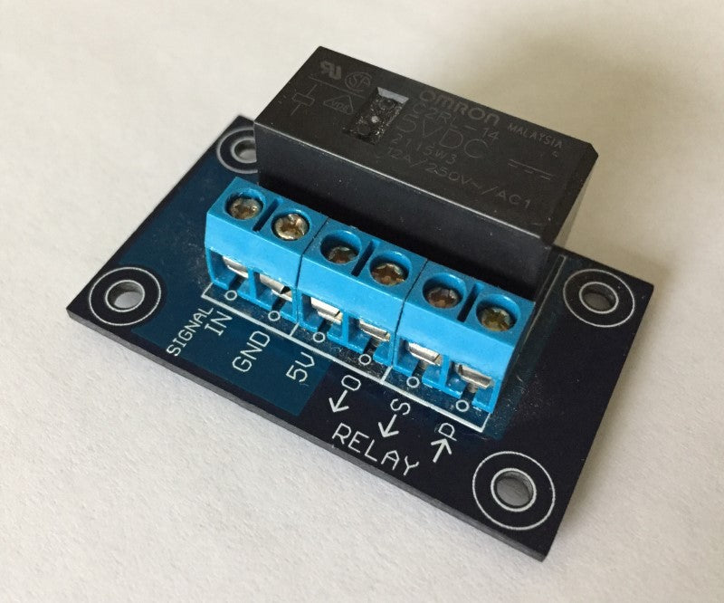
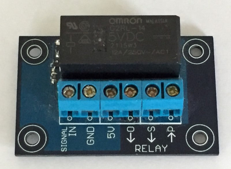
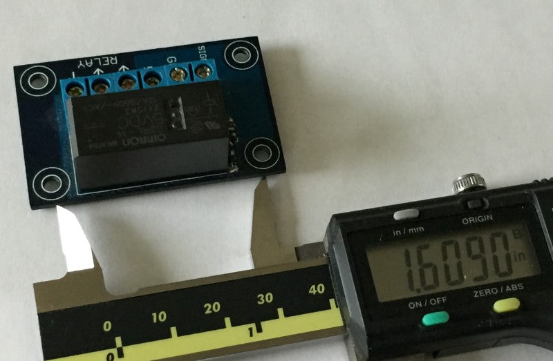
The relay board will turn on standard electrical devices up to 12 amps and 250 volts using a standard 5v signal.

Description:

A relay board acts like an automatic switch to turn on and off electrical devices and appliances. The relay board has the capability of turning on and off devices that typically plug in to the wall outlet, but many more types devices can be operated from this relay switch.

If a 5v signal is applied to the relay board, then the relay makes a connection between the P and O terminals and breaks the connection between the P and S terminals. Therefore, you can have things turned on in scenarios where the 5v is applied or if the 5v is not applied, depending on how it is wired.

Ask a question about the Relay Board to Switch on Electrical Devices:
Previously answered questions:

Click on the question to reveal the answer.
No previous questions. Be the first to ask a question about this product.
----
Related Tutorials
Thumbnail: greenLean instructional image Installing the Spoilboard on the greenLean CNC Machine
Here is a tutorial on setting and permanently mounting the Spoilboard on the greenLean 4x8 Vertical CNC Machine. We recommend you use a 2nd person to help you lift and place the board. You should also mount your machine to the wall before permanently attaching the Spoilboard.
thumbnail for assembling CNC closed-loop electronics for a customer Assembling Closed-Loop Electronics with a 7.5kW Spindle
Watch this video to learn about the assembly process of closed-loop CNC electronics, including component arrangement, wiring considerations, and challenges faced. Discover valuable insights and tips for ensuring proper functionality and effective shielding.
Thumbnail: USB Controller wired to one driver and one stepper motor Wiring the CNC Motion Electronics with the USB Interface
Here is a tutorial on connecting drivers and stepping motors to the USB Interface for CNC machines. We offer the USB interface/controller for those that have a laptop, or don't have a parallel port on their computer, and who prefer to use the Planet-CNC software. Here I show a video on the entire process to get your USB Interface connected to the stepper drivers and stepper motors correctly and in a simple and trouble free way.
----
Get Help with:
This Product
Orders
Tech Support
Sales
This Product
Order Query
Tech Support
Sales
Not logged in. Log In Register
Track Order(s)
View Order(s)
I Want to Schecule a One-On-One Paid Tech Support Session
Book an Appointment Pertaining to a BuildYourCNC Product (Free)
Ask a Quesion Below (Free):
Book an Appointment Pertaining Other Equipment ($60/half hour)
Book an Immedite Appointment Pertaining Other Equipment ($120/half hour)
Ask a Quesion Below (Free):
Waiting for response... I may not answer immediately, but I was notified on my cellular phone so my response is forthcoming. If I don't respond immediately, you can always go to the [My Account] page to see all of our chats at any time.