Use a proximity sensor switch to signal a machine (i.e. CNC router or laser machine) that it has reached an end or home position.
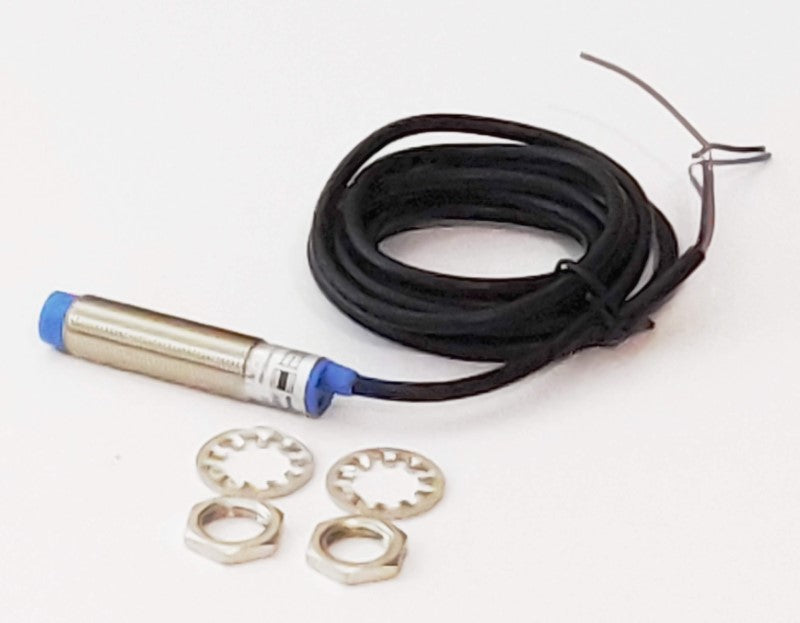
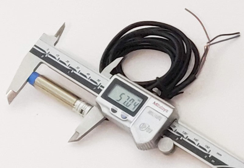
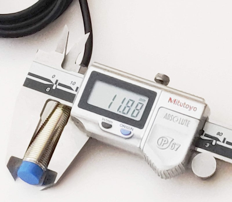
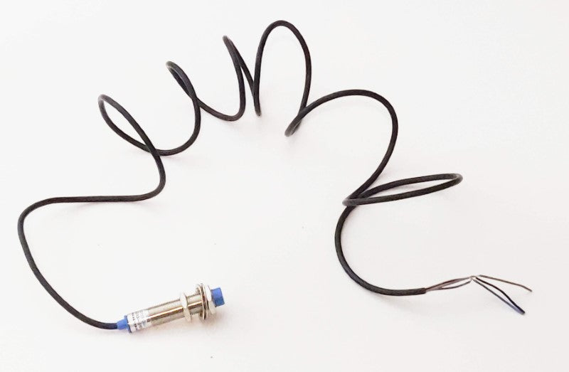
This is an inductive proximity sensor detection switch.
- Switch transistor type polarity: PNP, or NPN (depending on purchase option)- Voltage Range: 6VDC to 30VDC- Detection distance from a conductive material: 4mm- Normally Open type switch: Should be connected in Parallel or on a single input- 4mm distance activation
The three connections are Positive, negative (to essentially add current to the device), and the signal out which will connect to the input terminal. The brown wire is the positive wire and should be connected to the positive terminal of a power source. The blue wire is the negative wire and should be wired to the negative terminal of the same power source. The black wire will be connected to the input terminal on the controller or interface or breakout board of the CNC router or other type of machine. Typically, this sensor would use a 24-volt DC power supply that is used with the controller or interface.
The inductive proximity sensor will engage (become closed since this switch is normally open) when a material that can conduct electricity (conductive metals) nears the proximity sensor. When the proximity sensor is engaged, the signal (black wire) will go low (0 VDC or GND). The material will determine how near the material will be before the switch engages.
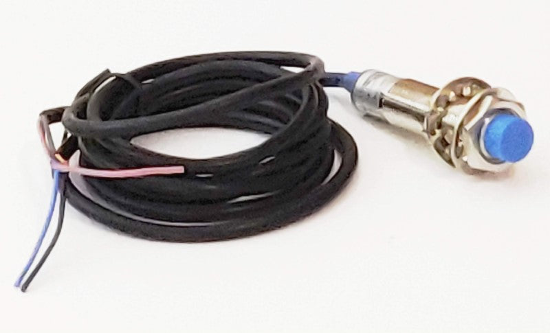
The proximity switch is activated when the ferrous metal comes close to the tip of the proximity switch.
How are Proximity Switches Used
Proximity switches are generally used in industrial machinery and manufacturing processes. Some kinds of industrial motion can be limited in movement using this proximity switch, typically to serve as the limits of a machine.
Proximity Switch Variations
The proximity switch comes in several flavors. One of which is how far the ferrous medal has to get to the end of the proximity switch before it engages. This proximity switch engages when ferrous metal gets 4mm from the tip of the proximity switch. The proximity switch will not engage when the ferrous metal comes close to the sides of the proximity switch. The other flavors that these proximity switches come in are normally closed (NC), normally open (NO), NPN, and PNP. Another feature of the proximity switch is the amount of voltage that can be used as the input power of the switch. This particular switch can be powered from between 6 volts and 36 volts so you can use the standard 24 volts that are used in typical industrial machinery.
Mounting the Proximity Switch
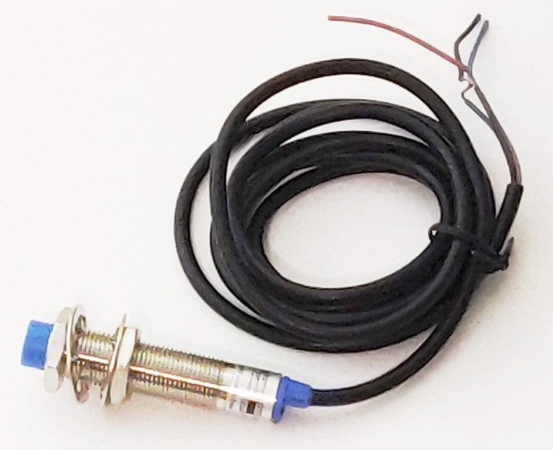
The proximity switch has a threaded feature along the cylindrical portion of the switch that will accept the nuts that come with the proximity switch. This allows you to position this switch axially in a hole drilled for it on the part that it mounts to on the machinery. The long thread allows this proximity switch to be adjusted to finely tune the limits of the machine.
There are a couple of ways you mount proximity switches on the machinery. The proximity switch can be mounted so that it rides on the moving part of the machinery and the ferrous metal that it uses to stop is static. Or, the proximity switch can be at the end of the machine (static) and the ferrous metal can be on the moving part of the machine, aligned so that it will meet at the tip of the proximity switch.
Proximity Switch Alternatives
Alternatives to proximity switches are mechanical types of switches like snap action on off-limit switches that can be wired as normally closed or normally open. The proximity switch can only be wired in the way it was designed. This proximity switch in particular is normally open (NO) and NPN.
The main difference between mechanical switches and the proximity switch is that the proximity switch is solid state and doesn't have any moving parts, meaning that the signal that is going to be produced by this proximity switch will be clean, whereas a mechanical switch can have a little bit of a bounce when it provides the signal to the controller or whatever you're hooking it up to. That can cause your machine to stop moving and think it hit a limit.
I talk a lot about the bouncing of mechanical buttons and switches in the following microcontroller videos. Take a look at those videos to understand more about what happens with the signal from a mechanical type of switch or button.
Button Debouncing Explanation 1
Button Debouncing Explanation 2
Proximity Switch Wiring
The proximity switch has three wires because the proximity switch requires power to operate. You're not going to see the typical wire colors. The wire colors are brown, blue, and black. The brown wire is the positive wire, the blue wire is the negative wire. Those two wires are powering the proximity switch. the black wire serves as the output signal. To test the proximity switch, connect it to a power supply between 6 and 36 volts. The blue connects to the V- of the power supply output and the brown connects to the V+ of the power supply output.
Now that you have the proximity switch powered, you can test it by moving a ferrous material (a piece of metal that is magnetic like steel or iron) close to it and you'll see that when it gets within 4 mm of the tip of the proximity switch, the red LED turns on.
You can test this with various metals and you'll notice that it doesn't turn on if you put the metal to its side or even touch it. It has to be in the front. The proximity switch can activate with metal chips, so be careful when milling that material. If you do have a lot of metal chips flying around, protect the proximity switch so that the chips won't interfere.
Let's take a look at the voltages when the switch is engaged and not engaged. The black wire would generally be wired so that the switch connects to the controller via a common V- rather than the V+. That is to say, the V- would be connected to all of the limit switches of the machine. When the proximity switch is not engaged the black wire will measure 24 volts, or somewhere around that number because it's a normally open switch. Now engage the switch by placing some metal in front of the proximity switch. This will close the circuit and you should show 0 volts (or thereabouts) between the V- and the black wire.
Now you can connect the proximity switch to a CNC controller. Here is what you need to do to configure this proximity switch to work with a CNC control software like Mach 3. You can use controllers like the Mach 3 USB controller or Pokeys57CNC controller which works with Mach 3 and Mach 4. Both of these controllers work with this particular proximity switch because the proximity switch is normally open and both of these controllers require a normally open proximity switch or a normally open limit switch. Connect the controller to the computer via a USB cable. The Mach 3 USB controller needs to be powered by a 24-volt power supply. V- is connected to the DC common or the DCM terminal. The V+, the red wire, is connected to the 24V or 24 volts terminal on the controller. The proximity switch blue and brown can also be connected to the DCM and 24V terminals respectively. The Mach3 USB controller has four inputs, IN1, IN2, IN3, and IN4. You can use any one of them, but you will need to enter that number into Mach3.
Proximity Switch Configuration with Mach3
The Mach3 USB controller will have a slow flashing red LED when the computer is connected to the controller. When you start Mach3 and press the RESET button, the red LED will stop flashing and just stay on. To configure the proximity switch, click on the CONFIG menu selection, click on PORTS & PINS, and then click on the INPUTS tab.
Pick the axis that will be used with this proximity sensor. For instance, if you have the proximity sensor on the X axis and will activate at the near end of the axis, change the parameters for the X++. Make sure port 3 and the PIN are the pins on the controller (i.e. IN2 is pin 2).
Click on the OK button and press the RESET button if Mach3 is in RESET mode (RESET is blinking).
To check if the configuration was completed correctly, click on the diagnostics tab and move a piece of metal close to the proximity sensor. The intended axis will light up. The axes are labeled M instead of the axis letter, for instance, M1++ is X++.