
Practical CNC Joinery Part 1 - Finger Joints
Share
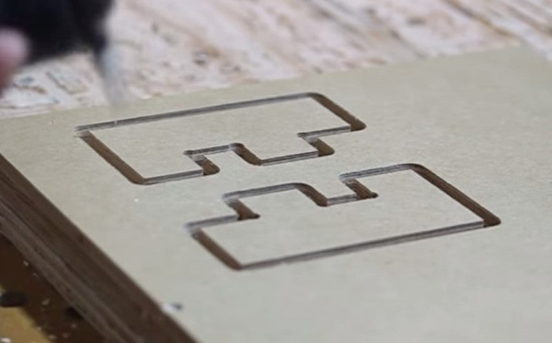
In this video we will demonstrate practical CNC wood joinery (practical meaning that there will be no need for special jigs). The material will be 3/4" sheet stock and the parts will be milled using a 3 axis CNC machine (Our greenBull). We will start with a simple joint, a finger joint. This joint - as it's name implies - is a joint that exhibits protrusions that measure the thickness of the wood, so that when put together, the corner is flush. Both pieces of wood will have these protrusions offset from each other so they both marry correctly. The aim is to make the fingers sized so that they are snug, but may allow some wood glue to be added to secure it permanently. The finger joint will not lock together unless the joint is very tight, but even with a tight fit, the joint (without glue) is not permanent. AutoCAD was used to design the pieces. The pieces are small to demonstrate the joint specifically. The joint is four inches wide with fingers one inch each. The sheet stock that we used actually measured .755 so we wanted to go a bit farther than .755 so it could compensate for the corner. We used .757 for all of these fingers. We then had four inches of width and the fingers protruding out .757 and each finger one inch wide. We took that same piece and rotated it 180 degrees. First we joined all the lines to create a polygon. Then we copied it and rotated it. Normally we would put a bit of a tolerance between the finger and make it a little bit thinner, but for the time we kept it at zero to see if the wood was forgiving enough to do this, if not we would need to add a thousandths of an inch displacement. The inside corners are not going to be perfectly square because we used a bit that is round. The bit had to do an overcut to be able to marry flat to the adjacent corner. This is also a good place for some glue to sit to provide added strength. The rounded corner also provides a relief for any stress at the corner, or stress cracks that could arise. Now we want to input the file in our CAM program to establish the machining operations. Save it as a DXF file. We'll be using CAMBAM for this. Once you have the two selected, create a roughing and finishing profile. We use styles to do this so we don't have to keep adjusting the parameters. Our roughing pass will have a clearance of .01 so when it comes to the finishing it will just shave off that little bit of material. We only want two holding tabs on these so we select both of them and change our holding tabs to minimum of two. The roughing pass actually does two passes and then the finishing pass does a single pass, just shaving off a little bit of material at the end. It will also do the overcut, and you can see inside the profile under the parameters that corner overcut is true, so this is an automatic machining operation that CAMBAM provides. Next we move to the CNC machine to cut it out. We have our stock setup, and we're going to zero the X, Y, and Z axes. It is not imperative that the Z axis is perfectly zeroed on the surface, we went as close as we could, but because this is not a locking joint and the joints are based mainly on the X and Y depths, it is really just going to be dependant on the X axis to get the thickness right so the Z axis doesn't really need to be perfect. After zeroing we are ready to start the machine. We cut out the two pieces and kept the holding tabs intact, because we wanted to test the mirroring of the two pieces. You can see in the video that there is a slight overcut, this is really a way for the short edge to meet and not conflict with the curve that could have happened because of the end mill. This is also a stress reliever. If you had a perfect inside corner, there is a stress point for cracks to happen so this actually works out really well. Our shop guy tells us this is a good place for glue to sit to make the piece even better. Remember we didn't put any tolerance between the pieces so they're right on. We want them to fit very snugly. You can put them together with a vice and they'll never come out. You may need to do a little bit more of an adjustment in the depths of these ends to make it a little deeper. These parts of the fingers don't protrude above the end-grain parts because it would be more difficult to make the surface smooth. If you're using a laminated product you wouldn't want to take any sanding off the laminated portion of it. The finger joint is now complete, and there is zero tolerance, so you may want to add a little bit of tolerance to make it easier and to have glue sit in between. Another aspect of this finger joint is that these ends are perfectly flush. There is no difference between them so this worked out very well. We also put this in a vice to tighten it up a little bit more. It was able to move a little bit but not enough to make it perfectly flush, so you want to move it back about .005 of an inch. That is how we make a finger joint with a CNC machine.