BuildYourCNC
Adjustable Rotary Limit Switch
Adjustable Rotary Limit Switch
Regular price
$13.95 USD
Regular price
Sale price
$13.95 USD
Unit price
per
Couldn't load pickup availability
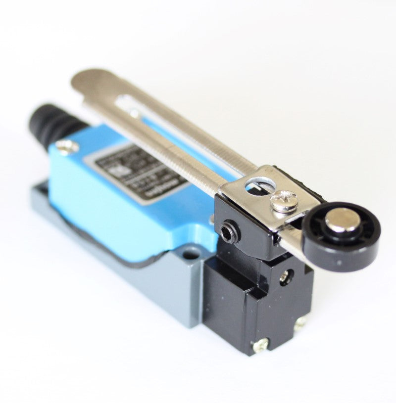
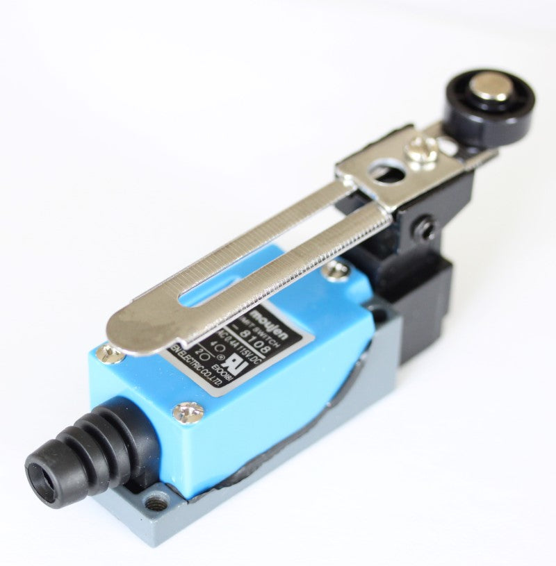
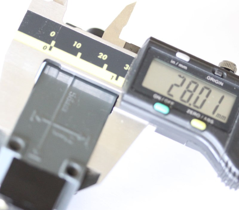
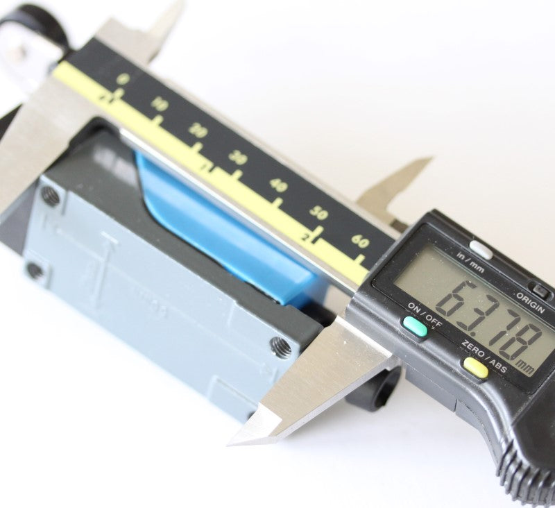
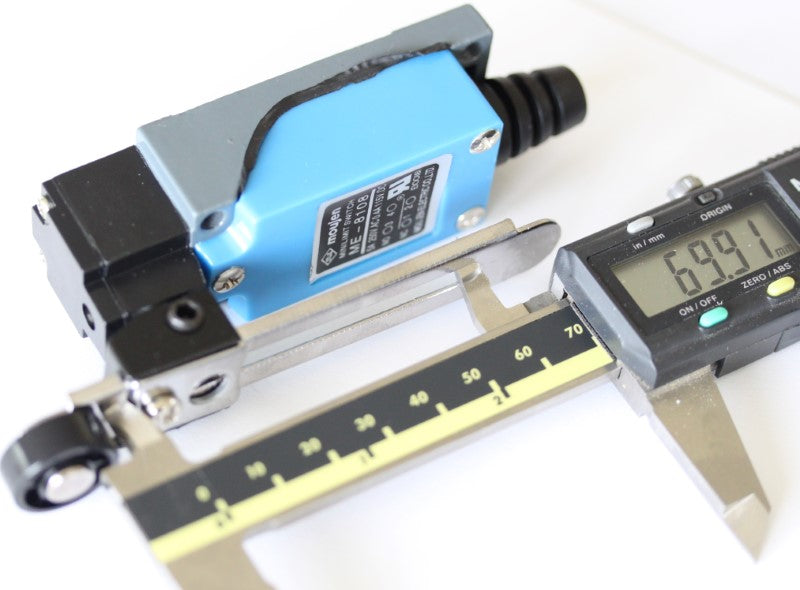
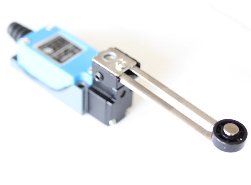
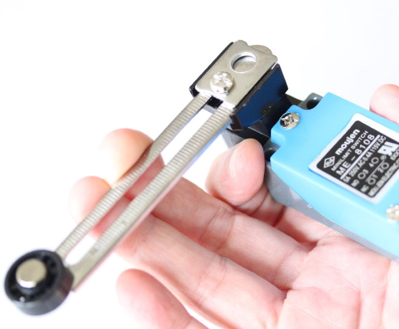
Use these larger extremely versatile rotary limit switches on your CNC. The action of these switches are rotational, so the lever arm can be mounted in a way that the switch can be actuated and not interfere with the structure that is pushing the lever. The lever angle of rotation can be rotated 90 degrees. There is a free spinning wheel at the end of the lever so the structure will not get hung up going in the reverse direction after actuating the switch. The switch can handle 5A (Amps of current) at 250 volts. In most cases, the wires will be digital level (5v), but can be connected to much high voltages if needed. No soldering needed since the wire connections are screw terminals. If you need a NO (Normally Open) connection, connect the circuit through the #3 and #4 terminals (for example, wire #3 to GND and #4 to the input pin). NC (Normally Closed) operation uses the #1 and #2 screw terminals. The #1 and #2 screw terminals are the two terminals closest to the cable strain relief. The #3 and #4 screw terminals are closest to the lever arm. Mounting holes are located at the back of this rotary limit switch and measure 21 mm on center and the long dimension is 56 mm on center. Here is how to wire the Adjustable Rotary Limit Switch to the Mach3 USB controller. In tis case, I am using the Adjustable Rotary Limit Switch, but any standard snap action limit switches that can be configured in NO (Normally Open) mode can be used. normally open (NO) mode, if used with a single input, must be connected in parallel. 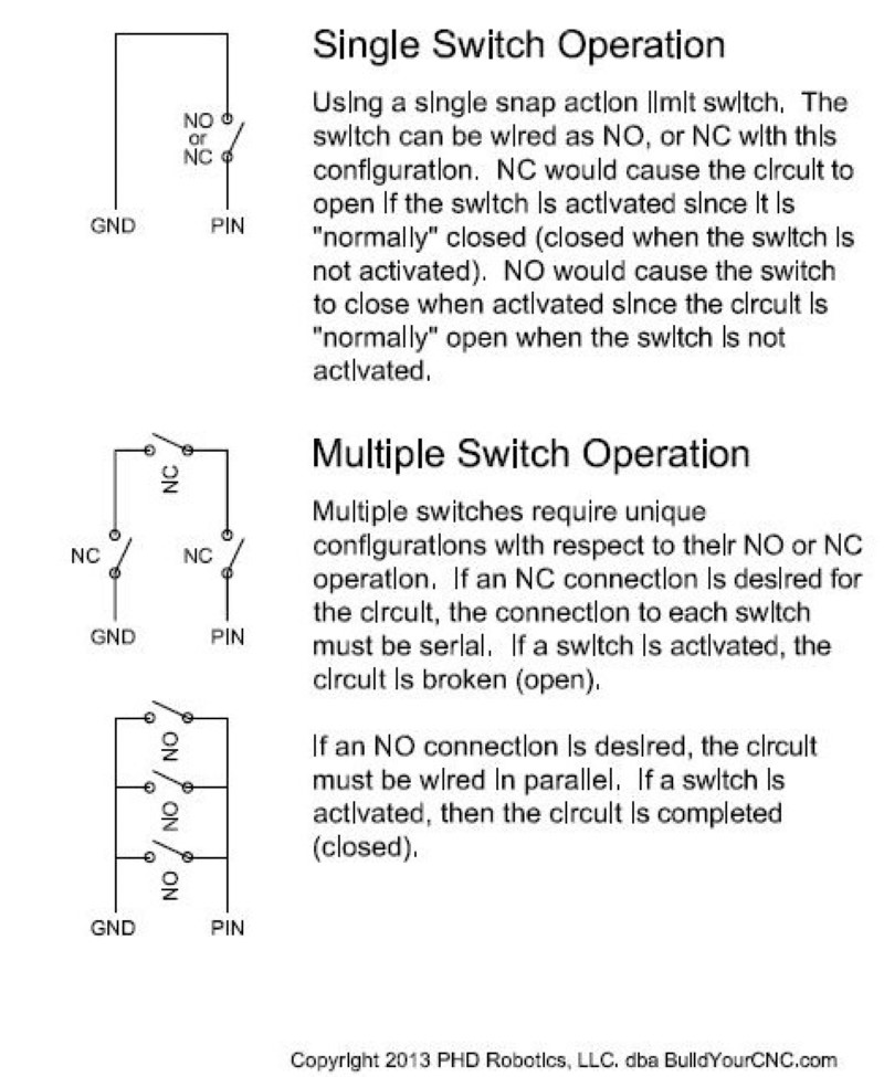 In Normally Open mode, when the limit switch is engaged, the circuit is closed, shorting the two NO (Normally Open) terminals.
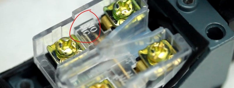
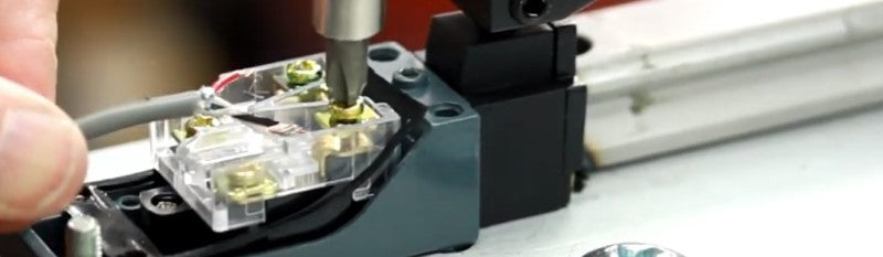
  After removing the terminal cover of the adjustable rotary limit switch, the terminals are revealed and if you look closely, you will see the NO and NC marking between the terminals. When the switch is engaged by moving the lever, you can see the mechanism moving between the NO and NC terminals. Use a shielded cable with two conductors at 22 or 24 AWG (gauge). The shielding is necessary since the input signals for CNC controllers are susceptible to interference. The shielding and the wire that is used for the ground must be wired together. That is to say, the shielding of the cable must be grounded at the controller or the power supply that is being used for the inputs.
  Wiring at the limit switch side (not at the controller) does not matter which NO terminal is used for the ground or the input since the switch will cause the two terminals to be connected. You may see a white wire in the shield and black wire in the picture. I am using a 3 conductor as this is what I had on hand. If you are using a cable with more than 2 conductors, make sure to ground the other unused conductors so those wires won't serve as antennas. Place the cover back onto the adjustable rotary limit switch and test the limit switch using the part of the machine that will be engaging the switch. You may need to adjust the length of the lever using the screw that secures the lever and the allen set screw that adjusts the angle of the lever.
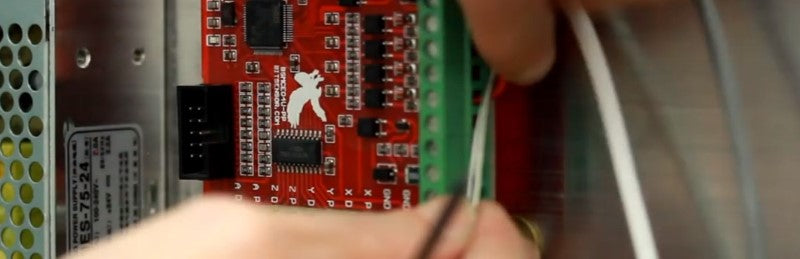
  The red wire from one side of the NO terminal on the adjustable rotary limit switch is connected to the IN1 terminal of the Mach3 USB controller. You can use any of the inputs on the controller, just remember to enable that input in Mach3.
  The black wire (ground wire), any other loose wires, and shielding in the limit switch cable is connected to the DCM terminal. In the image, I'm using a separate terminal strip so I can have space to connect multiple limit switches to the DCM terminal of the Mach3 USB Controller. This portion of the ground terminal strip will be connected to a 24VDC power supply ground, not to the 5VDC signal ground (Labeled GND on the Mach3 USB Controller).
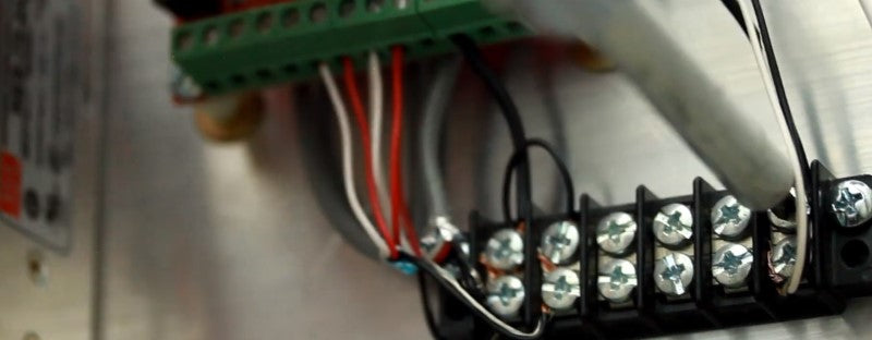
  The ground terminal strip is connected to the DCM (DC Common) terminal on the Mach3 USB Controller using a spare wire. The DCM terminal is the ground terminal for the 24VDC connection for the Inputs and Outputs for this controller that are located on this part of the controller.
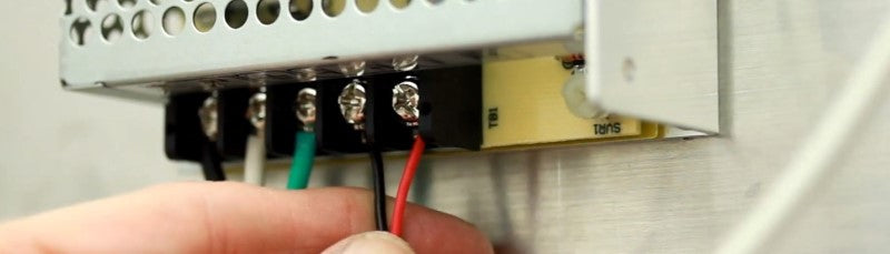
  Using a 2 conductor cable (sheilded cable is not necessary) is connected between a 24VDC power supply and the Mach3 ISB controller. The V+ of the 24VDC power supply is connected to the 24V terminal on the Mach3 USB controller and the V- (may also be labeled COM or GND) is connected to the DCM terminal of the Mach3 USB controller.
 With the default configuration downloaded from the Mach3 USB controller product page, testing the switch should engage the reset in Mach3. You can connect as many switches as you wish, using the parallel connection schema noted above, to the IN1 (Input #1) terminal of the Mach3 USB controller. Connect the next switches in the same way as the first switch. One side of the NO terminals connects to the IN1 (or to another limit switch on the same terminal that is used for the IN1 connection) on the Mach3 USB controller. The other side of the NO terminals, black wire and shielding, connects to the DCM terminal (in this case, to a terminal strip that is connected to the DCM terminal). Test the second, or other subsequently connected, limit switch to confirm proper function of the switch and Mach3 USB controller.
In Normally Open mode, when the limit switch is engaged, the circuit is closed, shorting the two NO (Normally Open) terminals. After removing the terminal cover of the adjustable rotary limit switch, the terminals are revealed and if you look closely, you will see the NO and NC marking between the terminals. When the switch is engaged by moving the lever, you can see the mechanism moving between the NO and NC terminals. Use a shielded cable with two conductors at 22 or 24 AWG (gauge). The shielding is necessary since the input signals for CNC controllers are susceptible to interference. The shielding and the wire that is used for the ground must be wired together. That is to say, the shielding of the cable must be grounded at the controller or the power supply that is being used for the inputs. Wiring at the limit switch side (not at the controller) does not matter which NO terminal is used for the ground or the input since the switch will cause the two terminals to be connected. You may see a white wire in the shield and black wire in the picture. I am using a 3 conductor as this is what I had on hand. If you are using a cable with more than 2 conductors, make sure to ground the other unused conductors so those wires won't serve as antennas. Place the cover back onto the adjustable rotary limit switch and test the limit switch using the part of the machine that will be engaging the switch. You may need to adjust the length of the lever using the screw that secures the lever and the allen set screw that adjusts the angle of the lever. The red wire from one side of the NO terminal on the adjustable rotary limit switch is connected to the IN1 terminal of the Mach3 USB controller. You can use any of the inputs on the controller, just remember to enable that input in Mach3. The black wire (ground wire), any other loose wires, and shielding in the limit switch cable is connected to the DCM terminal. In the image, I'm using a separate terminal strip so I can have space to connect multiple limit switches to the DCM terminal of the Mach3 USB Controller. This portion of the ground terminal strip will be connected to a 24VDC power supply ground, not to the 5VDC signal ground (Labeled GND on the Mach3 USB Controller). The ground terminal strip is connected to the DCM (DC Common) terminal on the Mach3 USB Controller using a spare wire. The DCM terminal is the ground terminal for the 24VDC connection for the Inputs and Outputs for this controller that are located on this part of the controller. Using a 2 conductor cable (sheilded cable is not necessary) is connected between a 24VDC power supply and the Mach3 ISB controller. The V+ of the 24VDC power supply is connected to the 24V terminal on the Mach3 USB controller and the V- (may also be labeled COM or GND) is connected to the DCM terminal of the Mach3 USB controller. With the default configuration downloaded from the Mach3 USB controller product page, testing the switch should engage the reset in Mach3. You can connect as many switches as you wish, using the parallel connection schema noted above, to the IN1 (Input #1) terminal of the Mach3 USB controller. Connect the next switches in the same way as the first switch. One side of the NO terminals connects to the IN1 (or to another limit switch on the same terminal that is used for the IN1 connection) on the Mach3 USB controller. The other side of the NO terminals, black wire and shielding, connects to the DCM terminal (in this case, to a terminal strip that is connected to the DCM terminal). Test the second, or other subsequently connected, limit switch to confirm proper function of the switch and Mach3 USB controller.