Instructions
1

Insert serrated hub to the stepper motor. Position the hub as shown and tighten the set screw very tightly.
2

Place the white plastic component on the stepper motor as shown. This piece serves as a guide for the filament and pressure against the serrated hub using a set screw. Make sure the holes align with the stepper motor.
3

Place the black aluminum heat sink to the top of the white plastic component as shown. Make sure the holes align with the white plastic component and the stepper motor.
4

Add the fan to the top of this assemble with the mounting holes aligned. Insert two long screws into the holes shown and loosely fasten these screws into the stepping motor.
5

Assemble hot end components the nozzle, aluminum block and threaded rod as shown. Pay close attention to the orientation of the threaded rod.
6

Insert the set screw into the hole shown. Do not drive the screw too much as the cartridge, or resistor will need to be inserted into the hole.
7

Insert the thermister or thermocouple (not included) mounting screw as shown loosely. Add the thermister between the screw and the aluminum block. Tighten the screw.
8

Wrap the thermister (or thermocouple) to the aluminum block as shown with Kapton tape. This will serve as a better hold for the thermister and position the thermister closer to the heated section of the hot end to provide a better temperature of the source of the extrusion.
9

Add the heating cartridge or resistor to the hold. Tighten the set screw so this heating element securely fastened in place.
10

Add two nuts to the threaded rod as shown allowing for a little space between them for the mounting plate. Add the black component on the threaded rod and add a nut on the other side of the threaded rod to secure the black component. Add a nut and screw to the black component in the neighboring hole. Allow a bit of space between the nut and screw for the mounting plate. Orient the black component in this assembly so that the holes are farther away as shown in the image.
11

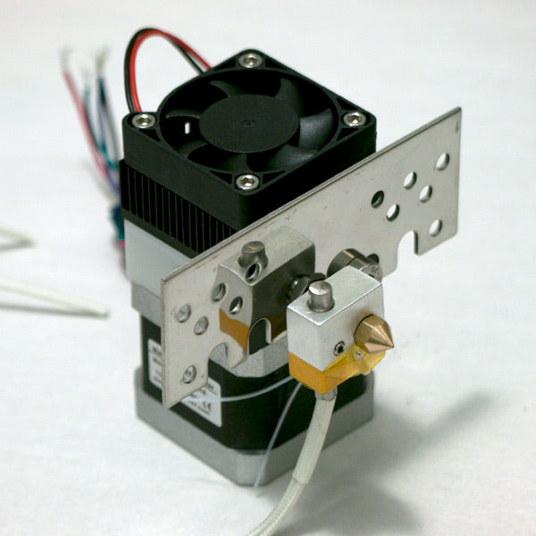
Add the mounting plate to the hot end assembly. Using a thin wrench, or pliers, tighten the nuts and screw around this plate to secure the plate in place. The assembly can be placed in multiple locations on this plate. Select the location that will serve the best for your machine.
12

13

14

Add the hot end and plate assembly to the motor and cooling assembly. Insert the last two long screws through the fan/heat sink and black component until it reaches the stepper motor mounting holes. Tighten all four long screws.


