Instructions
1

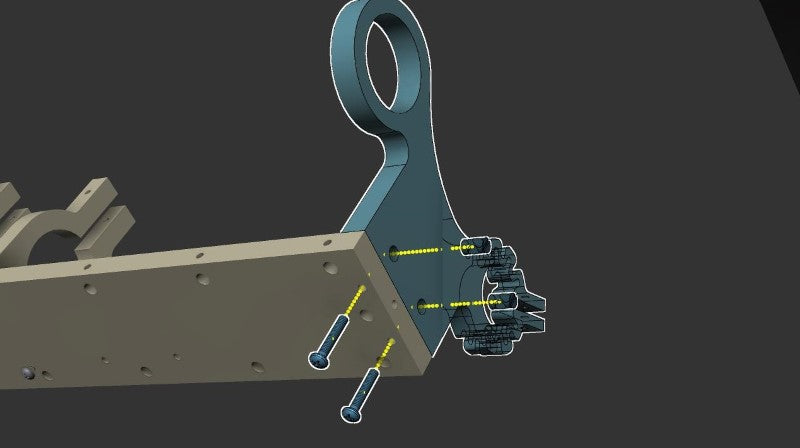
Attach the Spindle top mount to the z-axis back plate using two 1/4" by 1-1/2" screws and two cross dowels.
2

Attach the Spindle bottom mount to the z-axis back plate using two 1/4" by 1-1/2" screws and two cross dowels.
3

Attach the brush mount support to the z-axis back plate using two 1/4" by 1-1/2" screws and two cross dowels.
4

Attach the laser tube top mount to the z-axis back plate using two 1/4" by 1-1/2" screws and two cross dowels.
5

Loosely fasten the z-axis rail and right side rail support piece using six 1/4 x 1-1/2 inch screws and cross dowels.
6

Repeat the process from the previous step for the left side.
7

Position the bottom bearing mount on the top portion of the Z axis.
8

Assemble the z-axis bearing mounts using three 1/4" by 2-1/2" screws and cross dowels.
9

Insert one 1/2" ID (inside diameter) bearing into the bottom bearing mount along with a 1/2" small diameter washer.
10

Repeat the process from the previous step over the lead screw protruding from the top of the bearing mount.
11

Assemble two of the 1/2" coupling hubs with a coupling spider in the middle.
12

Install the flexible coupling (coupler) at the top portion of the lead screw. Make sure that the lead screw has just enough protrusion that it will be flush with the 1/2 coupling hub flat portion and does not protrude so much that the lead screw will interfere with the coupling spider.
13

Assemble the motor to the z-axis motor mount using four 1/4" x 1 - 1/2" screws and four quarter inch nuts.
14

Assemble the motor mount to the top bearing mount using four 1/4" by 2 - 1/2" screws and twelve 1/4" nuts.
15

Fasten the 1/4" nuts between the motor mount and the bearing mount to secure both pieces.
16

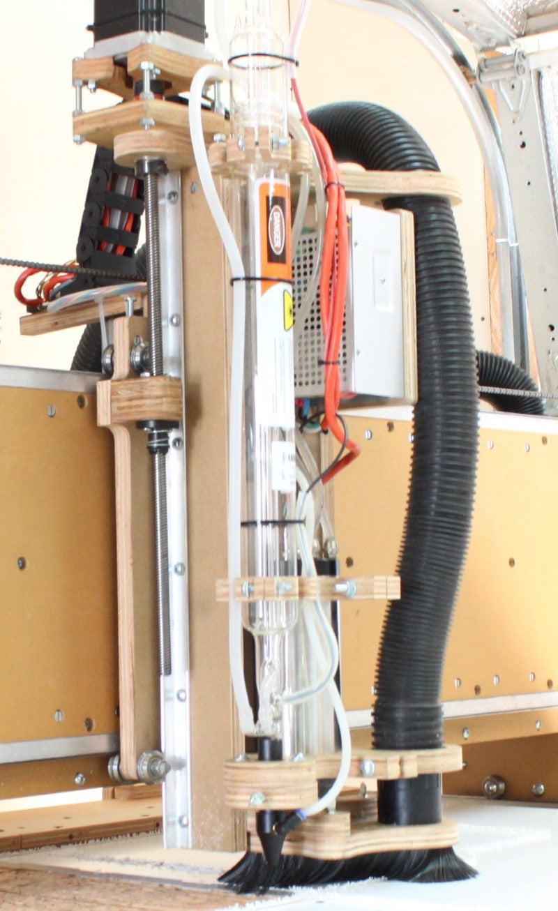
Insert the 2.2 kW Spindle through the top and bottom Spindle mounts.
17

Attach the air pump to the back plate of the z-axis using a zip tie.
18

Attach the power supply to the right rail support using four #6 by 1" screws, four #6 nuts and eight #8 washers.
19

Insert a 1/4" by 2-1/2" screw into the top spindle mount using a 1/4" nut and two 1/4" washers.
20

Insert a 1/4" by 2-1/2" screw into the bottom spindle mount using a 1/4" nut and two 1/4" washers.
21

Insert 1/4" by 1-1/2" thumb screws through the bottom brush support to attach the brush. The 1/4" insert nuts will be in the bottom face of the brush.
22

Insert the laser tube through the laser tube mounts with the laser lens facing down.
23

Secure the top laser tube mount using one 1/4" by 1-1/2" screw, two 1/4" washers, and one 1/4" nut.
24

Secure the bottom laser tube mount using one 1/4" by 1-1/2" screw, two 1/4" washers, and one 1/4" nut.
25

Secure the laser nozzle mount to the bottom spindle mount using two #8 x 2" screws, 2 #8 nuts, 2 1/4" washers and four #8 washers. Important Note: The washers that should be inserted with the top part of the screws are not shown in the image. Please use one 1/4" washer and one #8 washer for each screw.
26

Insert the laser nozzle as shown in the image.
27

Insert two 1/4" by 1-1/2" thumb screws into the nozzle mount with two cross dowels to adjust the laser nozzle.
28

The thumb screws are used to secure the position of the laser nozzle for the alignment process of the laser.
29

Maintenance Instructions Before each usage of the laser, make sure to check the laser lens in the nozzle on the bottom of the assembly. Loosen the thumb screw to free the nozzle, then separate the nozzle to expose the laser lens. Make sure the lens has been cleaned properly with a cloth so it is free of dust or any other debris. Also make sure clean water is always used. Periodically inspect the laser mounts to make sure the glass tube is not loose.


