Instructions
1

This video demonstrates an improvement made to the vacuum pump controller. The values for the thresholds and the actual sensor inches of Hg is now in decimal form with a precision of 2 decimal places.
2

This video describes the features of the vacuum pressure controller. All of the features are explained and demonstrated.
3

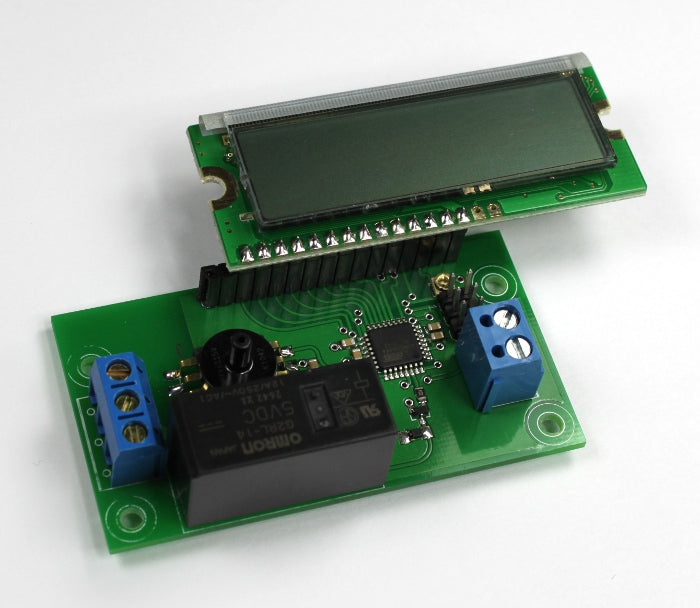
The vacuum pressure controller requires 5 volts of power. This power can come from the computer via a USB cable, or a 5 volt power adapter. The controller requires very little current to drive the relay on this board (Relay coil: 80 mA with a coil resistance of 62.5 ohms). If a computer USB cable is used, cut the cable and expose the red and black wires from the cable. The other wires and shielding can be removed, or cut short as they are not used. For both a USB cable, or adapter, the +5V wire (red wire in the USB cable) is fastened inside of the terminal closest to the LCD. The GND (black wire in the USB cable) is fasten to the terminal farthest from the LCD.
4

Adjust the low end threshold using a small screw driver at the left potentiometer trimmer. This will adjust the number labeled L: and is shown in inches of mercury (Hg). When the actual pressure is less than or equal to the low end threshold the relay will engage (send current to the coil of the relay and close the two terminals for NO-normally open operation.
5

Adjust the high end threshold using a small screwdriver at the left potentiometer trimmer. The high end threshold is labeled as H: and is shown as inches of mercury (Hg). When the actual pressure in the pressure sensor is greater than or equal to the high end threshold, the relay will disengage, or opening the terminals for NO (normally open) operation).
6

Use a tube that will fit over the pressure nozzle that has a diameter of 0.1165 inches (2.95mm). A silicone tube with a 1/16 inch inside diameter works well which stretches around the nozzle of the pressure sensor.
7

Insert the tube over the vacuum pressure sensor nozzle. This tube will connect to the device that holds the vacuum or the line that is connected between the vacuum pump and the tank. Make sure to use a check valve between the vacuum pump and the tank (or container/device that will hold the vacuum). A check valve is a device that only allows air to travel one way. This will prevent the vacuum from escaping the tank back into the vacuum pump. The pressure sensor hole should be fitted onto the tube after this check valve, or fitted directly onto the tank.
8

Use either an extension cord, or the power cable from the vacuum pump and remove the outside insulation. It is best to use an extension cord so that the main power cable for the vacuum pump is not damaged.
9

Cut the black (live) wire in the AC cable and expose the strands. The live/black wire is used as this is the safest wire to pass through the relay.
10

Insert one side of the black wire into the lower terminal. This terminal is the main terminal of the relay that will provide one side of the relay switch. Insert the other side of the black wire into the top position of the terminal. This position is the NO (normally open) position of the relay and will be open when the relay is disengaged (i.e. the two black wires will not be connected - open). When the relay is engaged, these positions will close (be connected). The middle terminal is a NC (normally closed) position with respect to the bottom terminal. Use this terminal if you want to reverse the on/off function of your vacuum pump.


