BuildYourCNC
STM32 Microcontroller and Interface Board
STM32 Microcontroller and Interface Board
Couldn't load pickup availability
Affiliate Links
Description: ARM Microcontrollers: Programming and Circuit Building Volume 1
Price: $39.00 USD
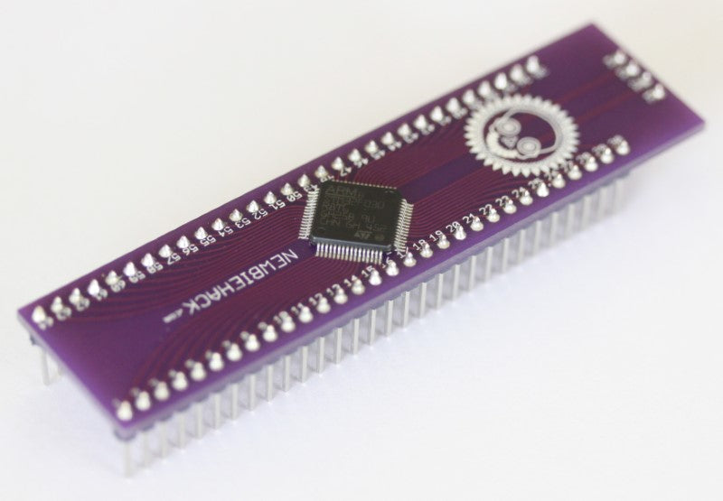
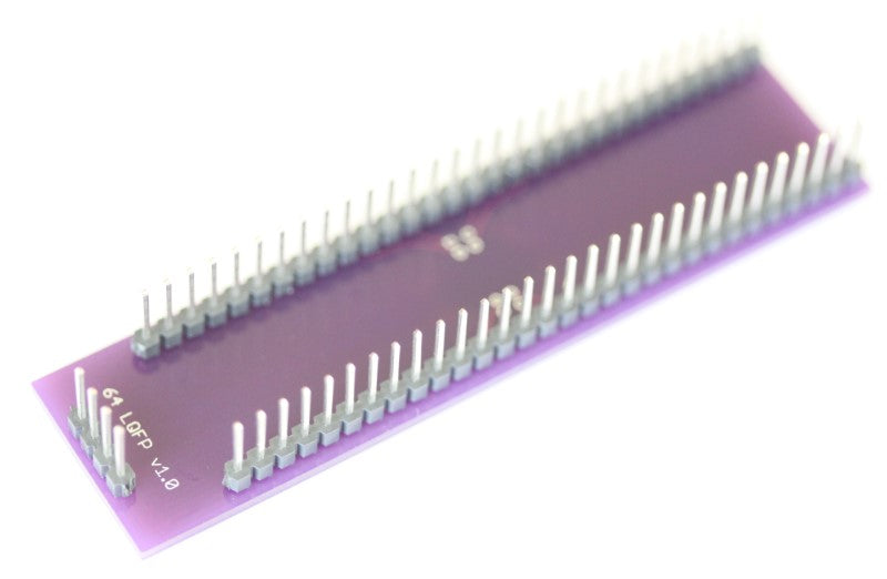
See ProductThis is an ARM Cortex-M0 microcontroller/processor and an interface card that plugs into a breadboard for direct prototyping. Get started with ARM embedded programming. The configuration of the main board with headers will fit on three breadboards enabling a vast array of tie strips for use in prototyping. The headers for the board are not soldered. This particular ARM processor has the following specifications: 32-bit of data bus width, maximum clock frequency of 48 MHz, 64 kB of Program Memory, 8 kB of RAM (SRAM), Analog to Digital precision is 12-bits, will accept voltages of 2.4v to 3.3v (3.3 volts is typical), package of the processor itself is 64 LQFP (Low profile Quad Flat Pack), 16 analog to digital channels, contains 55 I/O pins and 7 timers.
Share


Questions & Answers
Have a Question?
-
Will any of you boards support running dual spindles and using clearpath servos
Our Pokeys57CNC CNC Controller will control the Clearpath servos. Clearpath servos can work using standard step pulses and direction signals just like stepper motor drivers, so you can use a wide variety of controllers. The Pokeys47CNC has multiple relays on-board, but only one PWM for speed adjustment. If speed adjustment is not important, then you can use this board for more than one spindle. You can also use the Modbus connections (RS-485) in your VFD to control speed and other functions as a way to control multiple spindles. You can find the Pokeys57CNC controller here: https://www.buildyourcnc.com/item/electronicsAndMotors-electronic-component-breakout-Mach4-mach3-USB-ethernet-Board
-
Where can I find information on controlling my VFD through Mach4?
The best way to determine how to control your VFD using Mach4 is to read the MAch4 manual found here: http://www.machsupport.com/wp-content/uploads/2014/05/Mach4%20Installation%20Manual.pdf You will find that there a a few ways to control the spindle/VFD on your CNC machine or CNC Router. - The first and easiest is to have your VFD's power controlled by a relay. This will allow your spindle to have on/off control through Mach4 with an output pin. - The second is to have a controller output a DAC voltage between 0-10 volts to control speed on the VFD/Spindle. There is a termial on the VFD to receive this signal line. The controller will also have an output that outputs a high or low and that can control the on/off on the VFD. - The third, and more difficult of the three methods is to use a USB to Serial adapter (USB to USART or RS-485). The Computer plugs into the adapter using a USB cable and the adapter uses the RX/TX to connect to the VFD's terminals for communication. This will provide a great amount of control. Mach4 will need a plug-in to make this option work.
-
On the YL600 VFD which connections are DCM, ACM, V1 & Forward?
The DCM is DC common, or DC Ground which is used in conjunction with Forward (FWD, or FOR) to start the spindle in the forward direction. The ACM is the AC Common, or AC Ground (Alternating current, or in this case, a variable voltage for spindle speed). The ACM is used in conjunction with V1 to provide variable speed for the spindle. In order to use the terminals DCM/XGND, FOR/FWD, ACM/GND and V1/VI1, you will need to program the VFD to enable the terminals and disable the control panel. YL-600: Start/Stop - XGND or COM is paired with FWD or X4 (X5 for Reverse). Spindle Frequency: XGND or COM is paired with AI1 and uses a top end of 5VDC YL-620: Start/Stop - XGND is paired with FWD (REV for reverse) Spindle Frequency: GND (not XGND) and VI1. The Start/Stop portion of the control panel and terminals is separate from the spindle speed/frequency control panel and terminals. Each of these have a separate programming parameter. For the YL-600/620, the P00.01 parameter controls the source of the start/stop function. Settings for the P00.01 are: 0: Control Panel is used and the terminals are disabled. 1: Terminals are enabled and the Stop on the control panel is still enabled if needed. 2: Terminals are enabled and the Stop on the control panel is disabled. 3: Control is sourced from the MODBUS also specified as the RS-485 connection. This would be labeled as RX and TX (Receive and transmit) and uses the UART protocol (serial communication protocol). https://buildyourcnc.com/FAQ/13381 explains this in depth. Additional Information: DCM is Digital Common, ACM is Analog Common
-
I'm hooking up the VFD Controller to the USB controller to control the speed of the spindle. In your video you have the wire from the USB controller to the ACM of the VFD controller. The VFD controller I have is a XSY-AT1 model AT1-2200s. It does not have an ACM contact. It does however have a SP1 contact, is this where I land that wire?
You want to look for the analog input terminals in the wiring diagram in the manual for your VFD. I believe the VFD you have, the XSY-AT1 has three terminals that will accept an analog voltage to adjust the speed. These terminals are: COM or ACM - this is where the ACM from the controller will connect VI/CI - The AVI will connect to this terminal which is the actual voltage level that will determine the speed from 0 to 10V. 10V - This connects to the 10V terminal of the controller which will provide 10V to the controller allowing the top voltage reference for the controller. This will provide a 0 to 10V range for the AVI or VI/CI terminals, and if 5V is available on the VFD, then the range will be 0 to 5V. The parameter you need to change in the VFD is P10 which will change the source of the frequency, either the control panel which is the default (0 or 1, keys or potentiometer - dial, if that is available on the VFD), External analog signals which are the ACM, VI/CI and 10V/5V terminals in the VFD, or the RS485 which is a serial connection to the computer. You want to set this parameter to the External terminals which may be 2, but check your manual for the proper value.
-
If I bring my 6090 with Huanyang VFD/spindle and G540 can you wire vfd/540 together and get it talking to mach3 for me?
We can provide support to electronic components that we sell. We are unable to connect or diagnose electronics that we don't offer. Additional Information: We can provide solutions to products that we sell. For instance, we can inform how to connect a spindle's VFD to Mach3 using a RS-485 serial communication method.
-
I ordered a vacuum pump switch Approval Number:6WJ54852DT519742T my email is sm1omeara@yahoo.com can you send me a confirmation.
Please contact customerservice@buildyourcnc.com for help with this.
-
HOW TO CONTROL MY 2.2 KW SPINDLE VIA MACH3
You can go to our instructions on for the breakout board here: http://www.buildyourcnc.com/item/electronicsAndMotors-parallel-breakout-relay to get the information on turning the spindle on and off from the computer and mach3. Alternatively, you can connect the computer using RS485 serial to the inverter and send control commands that way. Additional Information: HOW TO CONTROL MY 2.2 KW SPINDLE VIA MACH3 usb Additional Information: Additional Information: Additional Information: How should I wire the Mach3 card (red, 4 axis) and the vfd (Yl620-a)? Additional Information: Additional Information: Additional Information:
-
Does the DAC card do scaling?
Can you please clarify which product you are referring to? USB controller or Parallel Breakout Board? Additional Information: The parallel breakout board. I have redFly with the GreenBull and I'm trying to control the spindle with LinuxCNC. The LinuxCNC spindle page you copy and pasted into my previous question doesn't answer any of the questions I asked. The redFly came without any paper work or documentation so I don't know if it has a DAC card or not. In the StepConf program of LinuxCNC you have examples on your LinuxCNC page of how to control the axes but nothing to control the spindle. Assigning spindle on to pin 14 does nothing. Additional Information: Typically, we use the relay on the parallel board to turn on the spindle. The RPM is handled by the manual setting on the VFD. Additional Information: If you need the speed to be handled by LinuxCNC, you will need to use the RS-485 TTL method. Additional Information: To connect your computer to the VFD, use a USB to RS-485 interface. RS-485 is just a serial interface protocol that uses standard 0 to +5 voltage TTL signal levels for communication (as opposed to RS-232 which uses -12v and +12 for signal level changes). Get a high quality interface to reduce any issues during the process. The VFD should have two terminals labeled RS+ and RS-. The USB to RS-485 adapter should have this labeled on it as well so the connections should be relatively straight forward. In the VFD parameters: PD001: 2 to accept RS485 commands PD002: 2 to accept frequency comands PD163: 1 to RS485 slave address:1 PD164: 1 RS485 baud rate 9600 PD165: 3 8bit, no parity, 1 stop bit Make sure LinuxCNC is also set accordingly: The PIN14 and PIN16 in the stepconf wizard should be set to unused because you don't want LinuxCNC to be outputting unnecessary signals. In the options step of the stepconf wizard: - Check the Include Halui user interface component. - Check the Include custom PyVCP GUI panel. - Check Spindle speed display You will want to edit the custom.hal text file located in the folder that was created from the stepconf wizard. Add these following lines: loadusr -Wn vfd hy_vfd -n vfd -d /dev/ttyUSB0 -p none -r 9600 net spindle-cmd-rpm-abs => vfd.speed-command net spindle-cw motion.spindle-forward => vfd.spindle-forward net spindle-ccw motion.spindle-reverse => vfd.spindle-reverse net on motion.spindle-on => vfd.spindle-on The dev folder in linux is typically used for interfacing devices and peripherals to the computer as these devices are communicated by simple memory addresses and these files are linked directly to these addresses. Under the custom_postgui.hal file, change this line: from: sets spindle-at-speed true to: net spindle-at-speed => cfd.spindle_at_speed and add the line: setp vfd.enable 1 When you start LinuxCNC, you will a spindle section with the reverse and forward buttons, a stop button and - and + buttons. Use these buttons to conform that the spindle is functioning properly. The spindle speed indicator in LinuxCNC will show the spindle speed and you can confirm that this is equal to the speed indicated on the VFD. Credit for this helpful information goes to: https://www.youtube.com/watch?v=1NF8EFoPlrk Additional information was also added by us to provide a better understanding.


