BuildYourCNC
Mini Prototyping Breadboard Self Adhesive - Green
Mini Prototyping Breadboard Self Adhesive - Green
Couldn't load pickup availability
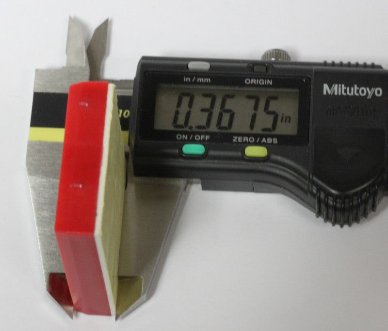
Mini Breadboard 17x10 with a self adhesive on the back. Green color. Measures 1.365 inches x 1.8 inches with a thickness of .375 inches. These modular breadboards are great for prototyping and tiny projects. They are half the size of a half-sized breadboard. Hence the term "mini breadboard". The mini breadboard comes with 170 tie points (17x10). Each breadboard measures 1.365 inches (34.67mm) x 1.8 inches (45.72mm) x .375 inches (9.52mm). The self adhesive on the back is easily removable for quick and seamless attachment to your device.
Share


Questions & Answers
Have a Question?
-
What settings does I use for controlling the spindle in StepCon/Linuxcnc?
LinuxCNC has excellent documents; however, I would like to offer our help in case you don't understand the information on that page. So, please use this FAQ (Question #: 13233) to state your questions by submitting additional information below. The LinuxCNC spindle control page is found here: http://linuxcnc.org/docs/html/examples/spindle.html Additional Information: After reading the LinuxCNC page my first questions would be can the spindle be controlled by PWM signal? Also, what pin on the parallel port would I set to Spindle Enable and FRW? Additional Information: To connect your computer to the VFD, use a USB to RS-485 interface. RS-485 is just a serial interface protocol that uses standard 0 to +5 voltage TTL signal levels for communication (as opposed to RS-232 which uses -12v and +12 for signal level changes). Get a high quality interface to reduce any issues during the process. The VFD should have two terminals labeled RS+ and RS-. The USB to RS-485 adapter should have this labeled on it as well so the connections should be relatively straight forward. In the VFD parameters: PD001: 2 to accept RS485 commands PD002: 2 to accept frequency comands PD163: 1 to RS485 slave address:1 PD164: 1 RS485 baud rate 9600 PD165: 3 8bit, no parity, 1 stop bit Make sure LinuxCNC is also set accordingly: The PIN14 and PIN16 in the stepconf wizard should be set to unused because you don't want LinuxCNC to be outputting unnecessary signals. In the options step of the stepconf wizard: - Check the Include Halui user interface component. - Check the Include custom PyVCP GUI panel. - Check Spindle speed display You will want to edit the custom.hal text file located in the folder that was created from the stepconf wizard. Add these following lines: loadusr -Wn vfd hy_vfd -n vfd -d /dev/ttyUSB0 -p none -r 9600 net spindle-cmd-rpm-abs => vfd.speed-command net spindle-cw motion.spindle-forward => vfd.spindle-forward net spindle-ccw motion.spindle-reverse => vfd.spindle-reverse net on motion.spindle-on => vfd.spindle-on The dev folder in linux is typically used for interfacing devices and peripherals to the computer as these devices are communicated by simple memory addresses and these files are linked directly to these addresses. Under the custom_postgui.hal file, change this line: from: sets spindle-at-speed true to: net spindle-at-speed => cfd.spindle_at_speed and add the line: setp vfd.enable 1 When you start LinuxCNC, you will a spindle section with the reverse and forward buttons, a stop button and - and + buttons. Use these buttons to conform that the spindle is functioning properly. The spindle speed indicator in LinuxCNC will show the spindle speed and you can confirm that this is equal to the speed indicated on the VFD. Credit for this helpful information goes to: https://www.youtube.com/watch?v=1NF8EFoPlrk Additional information was also added by us to provide a better understanding. Additional Information: linuxcnc??MACH3 ??? BL-MACH-V1.1????????? 0-10V ??????????????????????????????????? P1 ????????p1???????????????????hal??????????


