Instructions
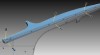
Example cutting plexiglass
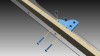
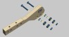
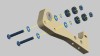
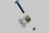
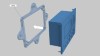
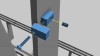
Attach the plexi assembly using 4 - 1/4" x 1" screws and 4 cross dowels.
Continue following the instructions from Step 1.
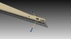
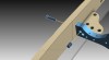
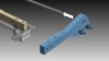
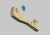
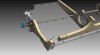
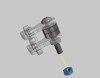
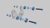
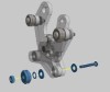
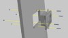
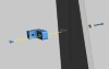
Attach the bearing block using 4 M6 x 16mm bolts and 4 1/4" washers.
Attach the bearing block using 4 M6 x 16mm bolts and 4 1/4" washers.
Attach the bearing block using 4 M6 x 16mm bolts and 4 1/4" washers.
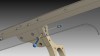
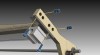
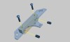
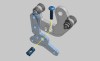
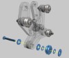
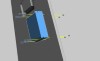
Attach the mount using 2 1/4" x 1" screws and 2 cross dowels.
Continue attaching the mount with 2 1/4" x 1-1/2" screws and 2 cross dowels.
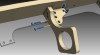
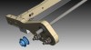
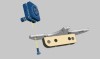
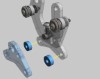
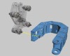
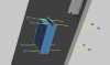
Attach to the mount using 4 #8 x 1-1/2" screws. Use 4 #8 washers in the front. Use 4 1/4" washers and 4 #8 nuts in the back.
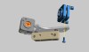
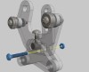
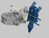
Attach the pictured assembly using 2 1/4" x 1-1/2" screws and 2 cross dowels.
Continue attaching the part using 1 1/4" x 1-1/2" screw and 1 cross dowel.
Continue attaching the mount using a 1/4" x 1" screw and a cross dowel.
Continue attaching the mount using 2 1/4" x 1-1/2" screws and 2 cross dowels.
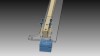
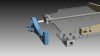
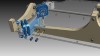
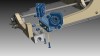
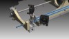
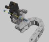
Secure the motor to the mount using 4 1/4" x 1-1/2" screws and 4 1/4" nuts.
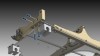
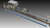
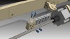
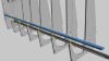
Use a 1/2" to 1/2" steel coupling to attach the motor shaft to the 1/2" rod.
On the opposite end, use a 1/2" to 1/2" steel coupling to attach the motor shaft to the 1/2" rod. Make sure the 1/2" rod is going through the hole in the laser tube bottom mount (as pictured).
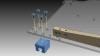
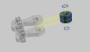
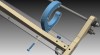
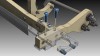
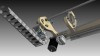
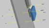
Place a 2" bearing into the groove on the part as picture.
Fasten using 2 5/16" x 2" screws, 2 5/16" washers, 2 5/16" thin (shim) washers, 4 5/16" idler bearings. and 2 5/16" nuts.
Attach the rod through the bearing as shown in the picture.
Attach using 2 1/4" x 1" screws and 2 cross dowels.
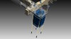
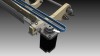
Place the drive pulley on the rod.
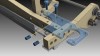
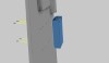
Place the bearing into the groove on the assembly as pictured.
Fasten using 2 5/16" x 2" screws, 4 5/16" washers, 2 5/16" thin (shim) washers, 4 5/16" idler bearings. and 2 5/16" nuts.
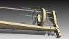
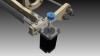
Place the mount through the rod as pictured.
Attach using 2 1/4" x 1" screws and 2 cross dowels.
Place the drive pulley on the rod as shown in the picture.
Attach the plexi piece using 2 1/4" x 1" screws and 2 cross dowels.
Attach the laser mount using 1 M6 x 16mm screw.
Attach the mount using an M6 x 16mm screw.
Attach the mirror mount using 2 1/4" x 1" screws and 2 cross dowels.
Attach the mirror mount using 2 1/4" x 1" screws and 2 cross dowels.
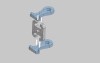
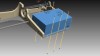
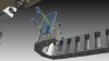
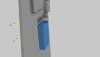
Attach the plexi pieces as shown in the figure to form the y-axis tensioner.
Attach 2 5/16" bearings and 2 shim washers.
Attach a 5/16" x 2" screw and 5/16" nut.
Fasten the 5/16" nut as shown in the previous figure.
Secure the assembly to the mount using a 1/4" x 2" screw.
Secure the power supply using 6 #8 x 1/4" screws and 6 #8 nuts.
Attach the holding mount using a 1/4" x 1-1/2" screw and cross dowel.
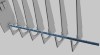
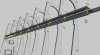
Attach the Y axis rails, using 8 #10 x 1-1/2" screws and 8 #10 nuts.
Attach using 4 #8 x 1-1/2" screws, 4 #8 washers on the front (plexi), 4 1/4" washers in the back, and 4 #8 nuts.
Attach using 2 1/4" x 1" screws and 2 cross dowels.
Attach using 2 1/4" x 1" screws and 2 cross dowels.
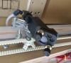
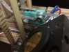
Secure the NEMA 24 425oz-in stepper motor with 4 #8 x 3/4" screws and 4 #8 nuts.
Attach the drive pulley onto the motor shaft.
Place the timing belt onto the pulley.
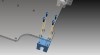
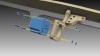
fasten 2 #8 x 1-1/2" screws into the bracket along with 2 5/16" V-Groove bearings, 2 #6 washers, 4 #8 washers, 2 acrylic spacers and 2 #8 nuts.
Fasten the plexi piece shown in the figure to the bearing assembly using a 1/4" x 1" screw and a 1/4" cross dowel.
Place the acrylic spacers between the piece shown in the figure.
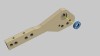
Insert a #8 x 1" screw through the 3 pieces of plexi and secure with a #8 nut.
Fasten a #8 x 1-1/2" screw with 3/16" V-Groove bearing, 2 #8 washers, 1 #6 washer, and a #8 nut.
Fasten a #8 x 1-1/2" screw to the 3/16" V-Groove bearing, with 3 #8 washers, and 2 #6 washers.
Fasten the .75" x 1" cable carrier bracket to the bearing assembly using a #8 nut.
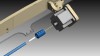
Install the laser nozzle head onto the bearing assembly using 2 #8 x 1/2" screws and 2 #8 nuts.
Add a #8 x 1" screw with 2 #8 washers and #8 nut for timing belt tension adjustment.
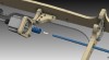
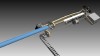
Picture of the timing belt attached to the hardware.
Picture showing the finished laser nozzle and timing belt assembly.
Attach the small cable carrier mount to male end of the 1" x .75" cable carrier. Fasten using 3 #8 x 1" screws and 3 #8 nut inserts.
Attach the small cable carrier mount to the plexi with 2 1/4" x 1" screws and 2 cross dowels.
Attach plexi to the large cable carrier female end using 3 #8 x 3/4" screws and 3 #8 nuts.
Attach the plexi to the top bearing assembly using 2 1/4" x 1" screws and 2 cross dowels.
Mount the 80 watt laser tube. Be cautious as the tube is fragile.
Place the laser control module into the plexi mount using 4 #6 washers and supplied nuts.
Secure the Laser Control Module into the structure using 4 #8 x 1" screws and 4 #8 nut inserts.
Attach the 6.0 amp driver to the inside of the left-side gantry piece using 4 #8 x 1-1/2" screws and 4 #8 nut inserts.
Attach the 3.0 amp driver to the inside of the left-side gantry piece using 4 #8 x 1-1/2" screws and 4 #8 nut inserts.
Attach the driver for the Laser Control Module on the inside using 4 #8 x 1" screws and 4 #8 nut inserts.
Attach the power supply using 4 M4 x 25mm screw.
Attach the 2nd power supply using 4 M4 x 25mm screws.
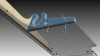
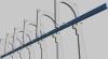
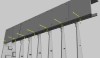
Install the guide rail using 20 #10 screws and 20 #10 nuts.
Install the top guide rail support using 6 1/4" x 1-1/2" screws and 6 cross dowels.
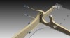
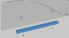
Attach the angled rail mount to the gantry using 2 1/4" x 1-1/2" screws and 2 cross dowels.
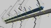
Attach the linear guide rail to the top rail mount using 20 #10 x 1-1/2" screws and 20 #10 x 1/4" nuts.
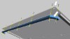
Attach the angular rail mount to the gantry using 6 1/4" x 1-1/2" screws and 6 cross dowels.
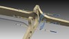
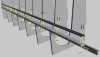
Attach the aluminum rail to the gantry mount using 18 1/4" x 1-1/2" screws and 18 1/4" nuts.
Attach the bottom angular rail mount using 6 1/4" x 1-1/2" screws and 6 cross dowels.
Attach the bottom aluminum rails using 18 1/4" x 1-1/2" screws and 18 1/4" nuts.
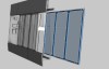
Attach the both top panels to the gantry ribs using 14 1/4" x 1-1/2" screws and 14 cross dowels.
Attach the tabs using a 1/4" x 1-1/2" and 1 cross dowel.
Attach the mount to the gantry rib using a #8 x 1-1/2" screw, #8 nut insert, and #8 washer.
Repeat previous step for remaining 6 mounts.
Attach the lower front panels using 14 1/4" x 1-1/2" screws and 14 cross dowels.
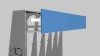
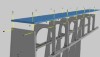
Illustration of where to place the front top panel.
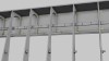
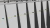
Insert 14 cross dowels into the slots as shown in the figure.
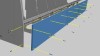
Attach the front top panels using 14 1/4" x 1-1/2" screws.
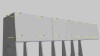
Attach the front top panel using 7 1/4" x 1-1/2" screws and 7 cross dowels.
Attach the front top panel using 7 1/4" x 1-1/2" screws and 7 cross dowels.
Slide the front plexi sliding door panel onto the angular rails.

Attach the window frame to the plexiglass using two #8 x 3/4" and two #8 insert nuts.
Attach the window frame to the plexiglass using two #8 x 3/4" and two #8 insert nuts.
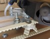
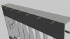
Attach the wood frame piece as shown in the image using 7 #8 x 3/4" screws and 7 #8 nut inserts. Notice the white arrows pointing to the adjustment hole on the plexiglass and the groove on the wood piece. The groove on the wood piece is larger on one side than on the other side, so make sure the larger groove aligns with the adjustment hole on the plexi.
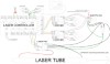
Wiring Diagram for Laser Control Unit
Click here for exploded view.
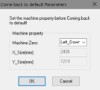
Laser controller parameters - default parameters
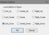
Controller position relative
Laser controller advanced functions
laser controller user parameters
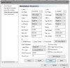
laser control manufacturer parameters
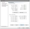
laser controller work parameters
laser controller work space
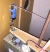
Suggested location for the X-Axis Rotary Limit switch at the zero location
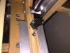
Y-Axis lower limit switch
Y-Axis upper limit switch
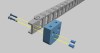
Y-Axis cable carrier connections
X-Axis cable carrier connection on the upper part of the gantry
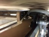
X-Axis Cable Carrier connection on the upper part of a rib of the main structure
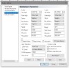
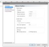
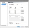
LaserCAD System Options - Manufacturer Parameters
These parameters shown are only a guide and the values that you should use for these parameters may be different. Make sure to go through the calibration on your machine to achieve the best precision and accuracy.
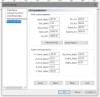
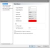
LaserCAD - System Options - User Parameters